Unlike thyristors or SCRs, triac circuits are able to switch both halves of an alternating waveform, making them ideal for many AC control and switching applications.
There are many circuits in which triacs can be used - often they are used for relatively low power switching and control applications in situations like domestic light dimmers, small heating controls and the like.
In these types of circuit the triac is a very useful device, enabling circuits to be designed using a minimum of components.
Triac circuits can be very straightforward requiring only a few components, and they are able to provide a good degree of control and switching, although they tend not to be used for high power levels where two discrete back to back thyristors provide better performance.
Triac technology
The triac can be considered as being two thyristors or SCRs back to back to accommodate both halves of an AC waveform cycle. Being a single device, this has considerable advantages, especially for domestic products where costs are of paramount importance.
The triac has the property that when a trigger is applied to the gate, the device turns on and remains conducting until the voltage across the anodes or main terminals of the device falls below a certain value - nominally when the supply voltage falls to nearly zero. This condition occurs when an alternating waveform crosses the zero voltage line, an din this way the triac is able to control each half waveform.
Triac switching waveform
Note on Triac Component Technology:
Triacs can be considered as back to back thyristors, but being contained within one device, their technology and operation is a little more complicated.
The triac can function as a switch - it could enable a trigger pulse of a low power switch to turn the triac on to control a much higher power levels that might be possible with a simple switch.
Simple triac switch circuit
In this circuit the resistor R1 may be 100R or more dependent upon the triac in question.
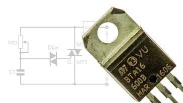
Triac variable power or dimmer circuit
One of the most popular triac circuits varies the phase on the input of the triac to control the power that can be dissipated into load. This is the form of circuit that is widely used in circuits for incandescent light dimmers in domestic applications. Sadly this simple circuit is not suitable for LEDs as it clips the leading edge of the waveform, and LEDs typically require the trailing edge to be cut.
This circuit operates because the capacitor and resistor network requires time for the capacitor to charge - the waveform at the junction of the capacitor and resistor is effectively delayed and this delays the turn on for the triac in the circuit. As the triac turns on part way through the half of each cycle, this means that the overall power in the circuit is reduced.
A basic triac circuit using phase of input waveform to control dissipated power in the load
Notice the diac placed in circuit next to the gate of the triac. This is required because the switching characteristics of triacs are not particularly symmetrical from one half waveform to the following half as detailed below. This results from the structure of the triac.
Issues with triac circuits
Triacs are not the complete solution to all AC switching requirements. Triacs have some issues when they are used in various circuits, and these must be accommodated when designing the circuits.
Some of get effects to be accommodated within the circuit design are mentioned below:
dV/dt effect: Triacs suffer from an issue sometimes called the rate effect or dV/dt effect. If either main terminal is subjected to a sharp change in voltage, exceeding the rated dV/dt rating, then can cause sufficient breakthrough to the gate to cause the triac to turn on. These transients can occur as a result of switching spikes or electrical discharges that are carried along the power lines. Another cause of transients can arise when driving inductive loads like motors. Here the line currents and voltages can be out of phase and under these circumstances large voltages can suddenly appear which are sufficient to exceed the triac dV/dt rating. It arises because the triac unlatches as its main terminal current falls to near-zero during each operating half-cycle.
A basic triac circuit with a transient snubber
This issue can resolved to a large degree by adding a transient suppressor across the line - a resistor, R1, possibly around 100R and series capacitor, C2, possibly around 10 nF or 100nF dependent upon the installation. Beware that the capacitor must be able to handle the voltage (and current) and the resistor must be large enough to dissipate the required energy, especially that of the voltage spike. For normal 240 volt power lines, the capacitor should have a working voltage of at least 400 volts and preferably more.
Backlash effect: This effect encountered in some triac circuits results when a potentiometer and capacitor is used to control the gate voltage.
It is found that if the potentiometer it turned to provide the minimum value, there is no leakage path for the triac MT1 to MT2 capacitance discharge, preventing the triac from turning on. The solution is to introduce a high value resistor to allow this capacitance to discharge.
Non-symetrical firing: Owing to the internal construction of trials, there are slight differences between the sections for covering the different half cycles. This leads to non-symmetrical firing of the triac and in turn this results in high levels of harmonics being generated which can be bad for EMC performance, etc. Although the action of the triac, even switching symmetrically will generate harmonics, the asymmetry will cause much higher levels to be generated giving rise to greater levels of interference. To help overcome this issue and provide a much more defined gate trigger signal for the triac circuit, a diac is normally placed in series with the gate.
A diac is able to improve the performance of the triac circuit because its switching characteristic is far more even than that of the triac. Since the diac prevents any gate current flowing until the diac trigger voltage of about 35 volts has reached, this makes the firing point of the triac more equal for both polarities.
Some years ago, trials that incorporated discs within the package were developed and sold. However, for some reason, these were not a commercial success and have been discontinued.
Harmonic filtering: Any switching circuit that switches during the course of the waveform, like a triac will generate harmonics. This is even worse if the triggering in non-symmetrical. These harmonics can give rise to interference that may affect the sorption of other electronic equipment into e vicinity, especially if wireless communications are used. Although it is best to remove any harmonics at source for EMC, even when a diac is fitted there is likely to be the need for some filtering to remove the harmonics.
A basic triac circuit with a harmonic / interference filter
For most triac circuits a simple LC filter will provide sufficient good filtering. A small series inductor, RFC1, and a capacitor, C2 across the triac will generally provide sufficient attenuation for many applications. A choke of around 100µH together with a 0.1µF capacitor will generally work adequately well. The choke should be able to withstand the current, and the capacitor must be able to withstand the voltage. If mains / power line voltage is being switched, as in the case of a light dimmer, the capacitor must be able to withstand the peak line voltage which is √2 times the RMS voltage plus a good margin to accommodate any transients that may come along the line. 400 volt rated capacitors are often used for 240 volt line systems.
There are many triac circuits that can be used. The basic circuits are very simple and provide good performance where this level of functionality is needed. The switching function can also be controlled via a processor enabling very intelligent forms of strike witching circuit to be developed.
Fact of the day: On this day in 1791, Samuel Morse, the inventor of the Morse telegraph system, and very accomplished portrait painter was born in Charlestown (now Charleston) Massachusetts USA.
Quote:Reality is the real business of physics. Albert Einstein
Point to ponder: It is impossible to make anything foolproof because fools are so ingenious.