
Discone Antenna Explained
The discone antenna provides a wide bandwidth with an omnidirectional radiation characteristic, making it ideal as a VHF / UHF scanner antenna or for military & monitoring activities.
Home » Antennas & Propagation » this page
Discone antenna includes:
Discone basics
Buy best discone antenna
The discone antenna or discone aerial is often used where an omnidirectional wide band or bandwidth RF antenna design is needed.
The discone antenna is used for many radio communication applications from radio scanning and monitoring for the commercial or military services to the home scanner enthusiasts.
In view of their size, weight and windage or wind resistance, these antennas are normally used for frequencies above 30 MHz, but on occasions they can be designed for lower frequency usage although the space required can be large.
Discone antenna basics
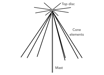
Although sometimes called a scanner antenna, the discone antenna receives its name from its shape: it consists of a top disc underneath which is a cone.
The disc and cone can be made from solid metal sheet, but this would increase the windage, i.e. wind resistance or wind loading and its weight.
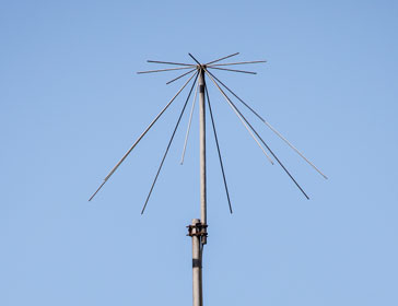
As a result, they are normally made using several rods to electrically simulate the disc and the cone. Often between six and sixteen rods are used, with most designs being within the lower region of the number of rods.
The discone antenna can operate over frequency ranges of up to 10:1 dependent upon the particular design, and it also offers a relatively low angle of radiation (and reception).
This makes it ideal for VHF / UHF applications as its greatest sensitivity is parallel or almost parallel to the Earth. However towards the top of its frequency range it is found that the angle of radiation increases slightly.
Although it is widely used for receiving applications, the discone antenna is less commonly used for transmitting. There are several reasons for this. Although it offers a wide bandwidth, it is not optimised for a particular band of frequencies and is less efficient than many other types of RF antenna design that can be used.
Additionally the wideband nature of the RF antenna means that spurious signals can be radiated more easily and the level of reflected power will vary over the operating range and may rise above acceptable limits in some areas. However with modern equipment, the filtering of the signal is normally very good, and this should not be too much of an issue.
Physical aspects of the discone
The basic RF discone antenna or scanner antenna design consists of three main components: the insulator, the cone elements and the disc elements.
Of the RF antenna components the insulator size governs a number of factors of the performance of the antenna. It is made from insulating material and acts to hold the disc and cone elements in place, keeping them a fixed distance apart. In fact this distance is one of the factors that determines the overall frequency range of the particular RF antenna design. It is represented by the distance D on the diagram.

Secondly, the cone elements should be a quarter wavelength at the minimum operating frequency. This can be calculated from the formula:
Where:
A is the length of the cone elements in millimetres.
f is the frequency in MHz
Thirdly the disc elements should be made to have an overall length of 0.7 of a quarter wavelength. This can be calculated from the formula:
Where:
B is the length of the disc elements in millimetres.
f is the frequency in MHz
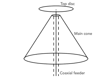
The diameter of the top of the cone is mainly dependent upon the diameter of the coaxial cable being used. This determines the upper frequency limit of the antenna. The smaller the diameter the higher the frequency. It is represented by the distance C on the diagram.
For many designs operating in the VHF / UHF region of the radio spectrum it is around 15 millimetres. The spacing between the cone and the disc should be about a quarter of the inner diameter of the cone, i.e. around three of four millimetres.
Additional vertical element on discone
Often discones will be seen with an additional vertical element attached to the top of the antenna. This is often the case when they are used as a scanner antenna.
This additional vertical element on the discone helps to extend the lower frequency response for the overall antenna, giving improved performance at lower frequencies.
The downside to the addition of the vertical element is that it can reduce the efficiency at higher frequencies.
I thought you might like to see these antennas . . . . . .
These antennas may prove to be ideal for your station:

25MHz-1300MHz,Ultra-Wideband Discone Antenna
Covering 25MHz to 1300MHz, this discone antenna is versatile for various communication needs. It is constructed from durable stainless steel.

Check out more items you might like from my Discone and wideband antennas.
More convenient to buy from Amazon.com? Check out Antennas and Amateur Radio Equipment on my Amazon Storefront.
Note: We make a small commission from any sales at no cost to you.
Discone operation
The way in which the discone operates is relatively complicated, but it can be envisaged in a simplified manner. The disc and cone elements sufficiently simulate an electrically complete disc and cone from which the energy is radiated. As a result the greater the number of elements, the better the simulation, although in reality there is a balance between performance, cost and wind resistance. Often around six elements are used, but the number is not critical.
In operation energy from the feeder meets the RF antenna and spreads over the surface of the cone from the apex towards the base until the vertical distance between the point on the cone and the disc is a quarter wavelength. In this way it is possible for the energy to be radiated or received efficiently.
The RF antenna radiates and receives energy that is vertically polarised, and the radiation pattern is omnidirectional in the horizontal plane. The antenna radiates most of the energy at a low angle which it maintains over the most of the operating range. Typically there is little change over a range of 5:1 and above this a slight increase in the angle.
With the feed point at the top of the RF antenna the current maximum point is also at the top. It is also found that below the minimum frequency the antenna presents a very bad mismatch to the feeder. However once the frequency rises above this point then a reasonable match to 50 ohm coax is maintained over virtually the whole of the band.
In terms of its operation requirements, the antenna is self contained. Unlike various vertical antennas it does not require the use of any ground connection, etc. Also the discone is an unbalanced antenna and can be fed directly from a coaxial feeder.
Places where discone antennas are used
Discone antennas find uses in many areas of radio communications, and especially at VHF and UHF for reception purposes.
At these frequencies their dimensions are manageable and their very wide bandwidth is particularly useful.
Monitoring public safety radio traffic: Discone antennas are often used by police and fire departments to monitor public safety radio traffic.
Receiving amateur radio signals: Discone antennas are a popular choice for amateur radio operators because of their wide bandwidth and omnidirectional coverage.
Antennas for scanners: Discone antennas are the preferred antenna of choice for people using scanners to monitor the VHF and UHF wavebands. Their very wide bandwidth means that a signals on very different frequencies can be received using a single antenna. Note that it is often illegal to listen to stations such as airband, emergency services, maritime communications, etc. Normally only the reception of broadcast stations, radio amateurs, and a few other services are allowed for general reception.
Military applications: The discone is ideal for many military applications, again at VHF and UHF where a wide bandwidth is required.
These are some of the more popular uses for discone antenna, although they find uses where wide bandwidth non-directional antennas are required.
The discone antenna is widely used at VHF and above where a wide band antenna is needed. Although not directive in the same way that a Yagi is directive, it provides a low angle of radiation that is ideal for terrestrial applications both for commercial and amateur / hobby radio communications applications.
 Written by Ian Poole .
Experienced electronics engineer and author.
More Antenna & Propagation Topics:
EM waves
Radio propagation
Ionospheric propagation
Ground wave
Meteor scatter
Tropospheric propagation
Antenna basics
Cubical quad
Dipole
Discone
Ferrite rod
Log periodic antenna
Parabolic reflector antenna
Phased array antennas
Vertical antennas
Yagi
Antenna grounding
Installation guidelines
TV antennas
Coax cable
Waveguide
VSWR
Antenna baluns
MIMO
Return to Antennas & Propagation menu . . .


