Understand all the fundamental aspects of the dipole antenna - how it operates, its length, bandwidth & the practical elements of how to make one & install it.
The dipole antenna or dipole aerial is one of the most important forms of RF antenna. The dipole can be used on its own, or it can form part of a more complicated antenna array.
The dipole aerial or antenna is widely used for a variety of types of radio communication, on its own, or incorporated into many other RF antenna designs where it forms the radiating or driven element for the overall antenna.
Basic dipole antenna
The dipole is relatively simple in its basic implementation and many of the basic calculations are quite straightforward. It is easy to design a basic dipole antenna that will operate on the HF, VHF and UHF sections of the radio frequency spectrum.
Not only is the dipole antenna used on its own, but it also forms the main 'driven' element of other antennas like the Yagi directional antenna that use seen everywhere in the form of television antennas and many more. It is also used as the driven element for many parabolic reflector antennas and it is used in many other antenna systems as well.
Dipole antenna basics
The name 'di-pole' indicates that the dipole antenna consists of two poles or items – two conductive elements.
Current flows in these two conductive elements and the current and the associated voltage causes an electromagnetic wave or radio signal to be radiated outwards from the antenna.
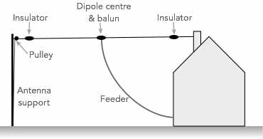
As seen the basic antenna consists of a radiating element that is split into two separate conductors. These are normally on the same axis, and the dipole antenna is normally split in the centre.
Power from a transmitter may be applied to be radiated, or power picked up by the antenna may be connected to a receiver. Normally the receiver or transmitter is connected to the dipole antenna via an intermediate feeder which enables the power to be transferred from one point to another.
The length of the radiating elements determine many of the properties of the dipole antenna: its feed impedance, centre operating frequency, whether it is a resonant antenna, etc.. As such the dipole length is an important aspect of the dipole antenna parameters.
Basic half wave dipole antenna
Dipole types
The most common form of the dipole antenna is the half wave dipole which gains its name because its length corresponds to an electrical half wavelength. However many other types of dipole antenna are also available.
The various different types or variants of the dipole antenna tend to be used in different applications - accordingly it can be seen that the dipole is a very flexible and useful antenna.
Half wave dipole antenna: The half wave dipole antenna is the one that is most widely used . This type of dipole antenna is resonant, operating at a point where it is an electrical half wavelength long.
The electrical half wavelength n the antenna is slightly shorter than that of a half wavelength in free space because of the effect of the wire in which the wave is travelling.
The half wave dipole is typically centre fed. This gives a low impedance feed point which is easy to manage. As the antenna is balanced, i.e. neither side linked to ground, it is necessary to use either balanced feeder, or if an unbalanced feeder such as coaxial cable is used, then a balun - a balanced to unbalanced transformer should be used.
The radiation pattern of the basic half wave dipole is relatively straightforward. It is at a maximum at right angles to the axis of the wire, and a minimum along the axis of the wire. If plotted, it forms a figure of eight type of plot.
Multiple half waves dipole antenna: Although the half wave dipole antenna is the most popular, it is possible to use a dipole antenna that is an odd multiple of half wavelengths long. The radiation pattern is very different, but it still operates effectively in this mode.
Again, this type of antenna is generally centre fed and again this provides a low feed impedance. It is worth noting that only by having an odd number of half wavelengths does a point of current maximum and voltage minimum occur at the centre to provide a low impedance feed point which enables easy feeding of the antenna.
This type of antenna can be useful when wanting to use the antenna at its fundamental frequency of resonance and then at three or more times this figure, making a multi-band dipole option.
Folded dipole antenna: As the name implies this form of the dipole aerial or dipole antenna is folded back on itself. Another half wave conductor is added in parallel with the original dipole elements so that one end is connected to the other presenting an DC short circuit. While still retaining the length between the ends of half a wavelength, the additional conductor enables the folded dipole to provide a higher feed impedance and wider bandwidth, both of which can be advantageous in many circumstances.
Short dipole: As the name implies, the short dipole antenna is one where the length is much shorter than that of half a wavelength. Where a dipole antenna is shorter than half a wavelength, the feed impedance starts to rise and its response is less dependent upon frequency changes. Its length also becomes smaller and this has many advantages.
A short dipole will need special feed arrangements to enable the much higher feed impedance to be accommodated. However, the antenna will tend to have similar characteristics over a wide bandwidth. Against this the efficiency level can be much lower than that of a dipole antenna which is larger in terms of its length in wavelengths.
Non-resonant dipole: A dipole antenna may be operated away from its resonant frequency and fed with a high impedance feeder. This enables it to operate over a much wider bandwidth.
Dipole feeding and feed impedance
One important characteristic of any antenna is its feed impedance, and the same is true of the dipole antenna.
The first point to note is that the dipole is a balanced antenna, i.e. neither of the two parts or sides of the antenna is connected to earth. This means that it must be fed using a balanced feeder or feed system.
This could be the use of a balanced feeder such as open wire or twin feeder - essentially two wires running in parallel. These feeders are sometimes used at HF and have very low levels of loss, although they are difficult to manage when entering buildings, etc as nearby objects can destroy the balance and increase loss.
It is for this reason that coaxial cable is widely used. However this is an unbalanced feeder and this requires the use of a balun - Balanced to unbalanced transformer. This can take many forms, and essentially it prevents RF running down the outer of the cable and giving rise to interference pickup for receivers, or interference to nearby users when used with a transmitter.
The other important factor is the feed impedance of the dipole. The standard feed impedance of a dipole is generally taken to be 73Ω, but this value is rarely seen as the impedance is changed by a number of different factors including the height above ground, wire thickness, and many other factors. The 73Ω value is the impedance in free space.
Feeding the dipole using a feed system with the correct impedance enables the maximum power transfer to take place, so understanding the feed impedance is important.
I thought these products may be of interest . . . . . .
These antennas and antenna components might be useful when installing your own HF antennas. They are available on AliExpress or check out my Amazon .com Storefront.
HF End Fed Wire Antenna 1‑30MHz
This end fed wire antenna uses a 1:49 balun to provide a good match. Aimed at used on the 40m, 20m, 15m, 10m, it should provide an SWR ≤ 1,5:1. Intended for low power use.
These antenna antenna insulators are ideal for use on any wire HF antenna, providing insulation at the ends where high voltages exist. The actual design is selected from the page when ordering as a variety of shapes (egg insulators to loner ribbed ones) are available to suit your needs.
Note: We make a small commission from any sales at no cost to you.
Dipole antenna applications
Dipole antennas are used in many areas, both on their own and as part of more complicated antennas where they can form the main radiating element. They are used in many forms of radio system from two way radio communications links, to broadcasting broadcast reception, general radio reception and very many more areas.
The dipole construction will depend upon the frequency, and also the way in which it will be used.
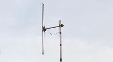
HF wire dipole: The dipole was widely used as a wire antenna at MF and HF where its performance enabled signals to be transmitted and received on these frequencies. Even today the wire dipole is frequently used for HF transmitting as in the case of amateur radio, etc. Typical example of an HF band dipole used for amateur radio
Typically the dipole was used as a half wave dipole, but on some frequencies a 3λ/2 version was also convenient as it enabled the dipole to be used at the fundamental frequency as well as at three times this frequency.
Part of Yagi antenna: The dipole antenna forms the driven element within a Yagi antenna. Often a folded dipole is used because the 'parasitic' elements within the Yagi cause the dipole feed impedance to fall. Using a folded dipole typically ensures the impedance match is improved.Not only is the Yagi antenna used for terrestrial television reception, but it is also used for many forms of two way radio communications, general radio reception, etc.
As omnidirectional vertical dipole: The dipole antenna is often used on its own as a vertically polarised antenna (in this case the dipole itself is vertical rather than the more usual horizontal format) to provide omnidirectional coverage.
A vertical folded dipole antenna
Often it may be used in this fashion for private mobile radio: these are two way radio communications systems used by businesses and other organisations including the emergency services to maintain contact.
Sometimes for various forms of professional two way radio communications, a series of vertical dipoles may be placed one above another so that the directional pattern of the overall antenna system is enhanced to give additional gain at right angles to the antenna, thereby providing improved coverage.
Driven element within a parabolic reflector: Parabolic reflector antennas need some form of driven element to radiate the antenna for the reflector to direct it in the required direction. Although a variety of radiating antenna types can be used, one option is the dipole antenna.
These antennas are often used for satellite communications, radio astronomy as well as for radio communications links of various types. These parabolic reflector antennas are often seen on mobile phone antennas where they provide a radio communication link to the core network. Parabolic reflector antennas are also used for satellite TV reception.
Tips for installing a dipole antenna
The way a dipole antenna is installed will depend a great deal on the frequencies for which it is intended, and hence its size.
Those for HF use will be much larger than those for VHF or UHF use, but despite this many of the basic principles and installation techniques remain the same.
Whatever the antenna, there are many steps that can be taken to ensure that the dipole antenna works to its best for the given location.
Notes on Installing an Antenna:
Although the actual type of antenna can be an important choice, probably more important is the isntallation - everything from where it is located, to the feeder used, grounding and much more.
The dipole antenna is a particularly important form of RF antenna which is very widely used for radio transmitting and receiving applications. The dipole is often used on its own as an RF antenna, but it also forms the essential element in many other types of RF antenna. As such it is the possibly the most important form of RF antenna.
Written by Ian Poole . Experienced electronics engineer and author.
Quote:Fools you are... who say you like to learn from your mistakes... I prefer to learn from the mistakes of others, and avoid the cost of my own. Otto von Bismarck
Point to ponder: The temperature of the gases in solar flares rises to many millions of degrees K. Sometimes far in excess of the temperatures at the centre of the Sun.


 Written by Ian Poole .


