
G5RV Multiband Ham Radio Antenna
The G5RV is a multiband HF wire antenna widely used by radio amateurs because it provides an effective antenna solution for multiple bands at little cost: details, construction, performance.
Dipole Antennas Include:
Dipole antenna basics
Current & voltage
Half wave dipole
Folded dipole
Short dipole
Doublet
Dipole length
Dipole feeds
Radiation pattern
Build HF ham dipole
Inverted V dipole
HF multiband fan dipole
HF multiband trap dipole
G5RV antenna
FM dipole design
The G5RV multiband wire HF antenna provides a very convenient, cost effective multiband antenna solution for HF ham radio communiations and as a result it has been popular for many years.
The G5RV antenna is based upon the doublet antenna concept and it was designed by Louis Varney, who held the amateur radio callsign, G5RV.
The design was originally devised in 1946, but it was not until 1958 that it was published when it appeared in the July 1958 RSGB Bulletin (the predecessor of the current RSGB RadCom journal.
Since then further notes appeared in RSGB Radio Communication in July 1984 and the antenna has been widely used and even manufactured by a variety of companies.
The G5RV HF multiband antenna operates on all amateur bands from 80 metres to 10 metres, although the VSWR is higher on some bands than others. It can be built from readily available components, or there are many versions that are available commercially.
An additional advantage, is that is does not occupy as much space as a full size 80 metre dipole and this can be an advantage for those with smaller areas for their antennas.
For those with limited space there is even a half size G5RV, often called the G5RV junior which is available, and it occupies half the space.
G5RV antenna basics
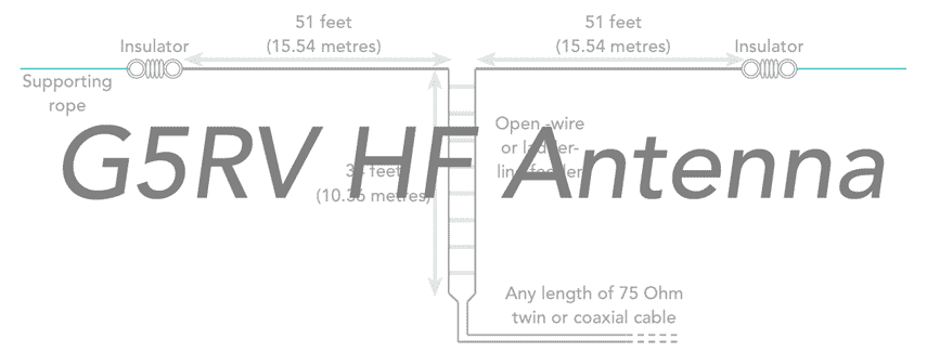
The G5RV antenna is an amateur radio centre fed doublet with a symmetric resonant feeder line, which serves as impedance matcher for a 50Ω coax cable to the transceiver.
There are two implementations of the G5RV antenna. The utilises 34 feet (10.36 metres) of open wire feeder, whilst the second uses any convenient length of open wire feeder which is connected directly to an antenna matching tuning unit.
The G5RV antenna that transitions directly to 75 Ω twin cable or coax is probably the more popular and it is shown below. However when using this option it is best to incorporate a balun in the circuit.
Also the transmitter will need to have a suitable tuning capability or external tuning unit by the transmitter to ensure that it can match the antenna.
Although it is meant to offer a reasonable load, the actual load on most frequencies is will fall outside the range which modern radio communications transmitters can tolerate without the PA protection circuitry reducing the power levels.

Although the G5RV antenna with 31 feet / 10.36 metres of open wire before transitioning to twin or coax is a convenient option, another solution is to use an antenna tuning unit.
Later adjustments took account of the different type of balanced feeders that could be used:
| Feeder Type | Length (Imperial) | Length (Metric) |
|---|---|---|
| Open Wire | 34 ft | 10.36 metres |
| Ladder line | 30.6 ft | 9.33 metres |
| TV 75Ω twin | 28 ft | 8,53 metres |
The original G5RV antenna design included the circuit for a suitable tuning unit, although there are many tuning units that are able to provide a good match. It is necessary to ensure that there is a balanced to unbalanced transition, i.e. a balun is used.

The antenna tuning matching unit provides two functions. One is to match the impedance because. Like any antenna, it will not give an exact match. The second is to provide the balanced to unbalanced transition.
Probably the best option is to use the antenna with an external or remote tuner unit and then the run though any building can be coaxial cable with a low VSWR.
I thought these products may be of interest . . . . . .
These antennas and antenna components might be useful when installing your own HF antennas. They are available on AliExpress or check out my Amazon .com Storefront.

HF End Fed Wire Antenna 1‑30MHz
This end fed wire antenna uses a 1:49 balun to provide a good match. Aimed at used on the 40m, 20m, 15m, 10m, it should provide an SWR ≤ 1,5:1. Intended for low power use.

Ceramic HF Antenna Insulators
These antenna antenna insulators are ideal for use on any wire HF antenna, providing insulation at the ends where high voltages exist. The actual design is selected from the page when ordering as a variety of shapes (egg insulators to loner ribbed ones) are available to suit your needs.

500W 1:1 Waterproof HF Balun for 160m - 6m Bands
A waterproof balun and dipole centre suitable for use with a standard dipole or inverted V dipole. 1:1 turns ratio to preserve the impedance match.

WINDCAMP-Portable Dipole Antenna for Amateur Radio/h3>
This dipole covers 5 - 55MHz and includes premarked resonant points for the different amateur radio bands. Ideal for POTA & SOTA.
Check out more items you might like from our Antennas, Tuners & Meters store.
More convenient to buy from Amazon.com? Check out my Amazon Storefront.
Note: We make a small commission from any sales at no cost to you.
G5RV antenna operation
The G5RV antenna operates over a wide band and is able to provide a reasonable match on most of the amateur radio bands. The antenna was originally designed in 1946 when the number of bands was much less than it is now. In fact it was designed to meet the needs of the then bands: 80 metres, 40 metres, 20 metres and 10 metres. At this time, even 15 metres was not an allocated amateur radio band.
In view of the number of different bands on which the antenna operates, the way in which it works is slightly different, i.e. the number of wavelengths in each section and hence its performance.
- 3.5 MHz, 80 metres: On 80 metres the G5RV antenna uses the flat top as well as about 5 metres of the matching section to form a half wave dipole. As a result it presents a reactive load it its input.
- 7 MHz, 40 metres: On 40 metres the G5RV antenna operates using the top section plus nearly 5 metres of the matching section and it operates as a partially folded collinear array with two half waves in phase. Again the antenna presents a reactive load to any transmitter at its input.
- 10 MHz, 30 metres: On this band the G5RV operates as two half waves in phase and as a result it presents a very reactive load at the input.
- 14 MHz, 20 metres: This is said to be the band for which the antenna was originally designed. It operates as a 3 λ / 2 dipole and presents a resistive load of about 90 Ω at its input. This provided a good match to the 75 Ω coax that was widely used at the time.
- 18 MHz, 17 metres: The G5RV performs as two in phase full wave antennas which extend slightly into the feeder section. The antenna is slightly reactive, but presents a high impedance in view of the top section being fed at a high voltage point.
- 21 MHz, 15 metres: The antenna performs as as a 5 λ / 2 antenna. As it represents an odd number of wavelengths it is fed at a current node and it is only slightly reactive.
- 24 MHz, 12 metres: The G5RV performs as a slightly long 5 λ / 2 antenna and as such it is slightly reactive, but the overall impedance is not too high.
- 28 MHz, 10 metres: The antenna acts as two 3λ / 2 sections fed in phase. It gives a high impedance load which is slightly reactive.
The antenna is very much a compromise and it presents a variety of different loads to the transmitter. Whilst this may have been acceptable in the days of vacuum tubes / valves when it was designed, modern semiconductor PAs do not like this variety of loads and an antenna tuning unit must be used.In terms of radiation, the G5RV antenna provides performance almost equivalent to a dipole on 80 and 40 metres. On 20 metres the extended length means that the radiation lobes provide a lower angle of radiation in some direction and therefore it can favour long distance signals in the direction of the lobes as these will tend to arrive at a low angle. In fact Louis Varney always maintained that the antenna worked best on 20 metres.
G5RV antenna and balun
The G5RV antenna is a form of doublet antenna which has a balanced format, i.e. neither of the two feed wires is earthed. However one of the main methods of feeding the antenna is to use coaxial cable, which by its very nature is unbalanced.
In order to feed the antenna and have the conversion from the balanced open wire or ribbon cable feeder to coax requires the use of a balun - a balanced to unbalanced transformer.
The balun can take many forms. It could be constructed around a ferrite core, but more usually for this type of application, the balun can consist of 8 to 10 turns of the coaxial cable with around 6 inch diameter, if the bend radius of the coax will tolerate this. Thhis configuration acts as an RF choke and prevents any common mode currents flowing along the coax.
Although it adds weight to the G5RV antenna, this approach is often very successfully used.
G5RV antenna & VSWR
Obviously in 1946, Louis Varney did not have access to any computer modelling for his G5RV antenna. In more recent years computer simulations for the antenna show that it provides a high level of VSWR on most bands. Typical figures might be: 6.5:1 on 3.7 MHz, 5.5:1 on 7.1 MHz, 2.4:1 on 14.2 MHz, 4.6:1 on 21.2 MHz and above 10:1 on 28 MHz and other HF amateur radio bands.
This means that with modern transmitters with semiconductor power amplifiers it is essential to use an antenna tuning unit. Without this, the power amplifier will see an unacceptably high level of VSWR and will either be possibly be destroyed if no VSWR protection is incorporated into the circuit, or the protection circuitry will reduce the output to a level where the levels of current and voltage resulting from the high SWR can be tolerated.
Even when an ATU is used with the G5RV antenna the level of reflected power can result in high levels of loss if the coaxial feeder does not have a sufficiently low loss. If the loss of the coaxial feeder is high, then the VSWR will not look as bad because the forward is attenuated, and the reflected power is attenuated, again. This means that the reflected power seen at the transmitter is much lower making any metering think that the VSWR is not nearly as bad.
G5RV performance and choice
The G5RV antenna has many advantages, but when selecting an antenna it is worth understanding all the trade-offs against the advantages.
G5RV HF antenna advantages
- Multiband capability: The G5RV antenna provide a multiband capability. It is able to operate on all amateur bands between 80 metres and 10 metres.
- Simple construction: The G5RV can be made quite easily using components available from amateur radio stores and outlets.
- Low cost: It is possible to construct a G5RV antenna for very little cost - there are no high price items
G5RV HF antenna disadvantages
- Compromise antenna: The antenna does not provide a good match on many frequencies - an antenna tuning unit is always very advisable.
- Beware loss on coax: With some commercially manufactured antennas may use relatively lossy coax cable. This may give a better VSWR figure at the transmitter, but it will result in signal loss. Check before buying, or if making a G5RV yourself, use low loss coax.
- Directive pattern: The directional pattern of the antenna will vary according to the frequencies in use. This may not be a particular issue in many cases.
The G5RV antenna was initially developed before the advent of semiconductor technology, when valves / thermionic tubes were used. These devices were relatively tolerant of poor VSWR, and therefore high levels of VSWR were often acceptable in antennas. Today with the use of semiconductor output devices, VSWR is more important, and therefore an antenna matching unit should always be used to protect the PA.
Half size G5RV antenna
Even though the traditional G5RV is smaller than a half wave dipole for its lowest band (80 metres), this can still be too large for some stations. To meet this need, an antenna called the half size G5RV or G5RV junior antenna was developed. Rather than covering the HF bands from 80 to 10 metres, the G5RV junior only covers the bands from 40 metres to 10 metres and is about half the size.
Writing in 1966, Louis Varney stated that it is possible to scale the antenna down to half size - both the top wire section and the length of feeder stub need to be shortened in this manner.
This means that the top section of the antenna should be 51 feet or 15.5 metres and the matching twin feeder can be 17 feet or 5.2 metres in the case of open wire feeder, or 15 feet or 4.6 metres in the case of using 300Ω ribbon feeder.

In the same way that the both sides of the feeder can be strapped together and the whole normal size G5RV antenna used with a good ATU to provide coverage of 160 metres (Top Band), so too the same technique can be used with the half sized G5RV antenna to provide 80 metre coverage.
This antenna, like its full sized big brother operates with high levels of VSWR and therefore, for any transmitting radio communications, the antenna tuning unit is essential.
The G5RV antenna has much going for it and it can provide a solution for many situations where a low cost multiband wire antenna is needed for HF ham radio communications. The antenna has been used for many years by thousands of people and given some useful results, although the variable impedance presented to the transmitter means that with current semiconductor based transceivers an antenna tuning unit is essential to keep the VSWR within tolerable levels. Also the use of low loss coax is required to keep the loss levels down when operating with the high levels of VSWR seen on virtually all bands.
 Written by Ian Poole .
Experienced electronics engineer and author.
More Antenna & Propagation Topics:
EM waves
Radio propagation
Ionospheric propagation
Ground wave
Meteor scatter
Tropospheric propagation
Antenna basics
Cubical quad
Dipole
Discone
Ferrite rod
Log periodic antenna
Parabolic reflector antenna
Phased array antennas
Vertical antennas
Yagi
Antenna grounding
Installation guidelines
TV antennas
Coax cable
Waveguide
VSWR
Antenna baluns
MIMO
Return to Antennas & Propagation menu . . .


