Build an HF Ham Radio Dipole Antenna
It is easy to build, construct and erect a dipole antenna for the HF bands: 160, 80, 40, 20, 15, 10 metres, etc using a few simple components at a minimal cost and get great results.
Home » Antennas & Propagation » this page
Dipole Antennas Include:
Dipole antenna basics
Current & voltage
Half wave dipole
Folded dipole
Short dipole
Doublet
Dipole length
Dipole feeds
Radiation pattern
Build HF ham dipole
Inverted V dipole
HF multiband fan dipole
HF multiband trap dipole
G5RV antenna
FM dipole design
Dipoles are one of the simplest antennas to build or construct and erect for the HF amateur radio bands, and on top of this they can be very effective. Dipoles are widely used on bands like 80 metres, 40 metres, 20 metres, 15 metres and 10 metres where they can provide excellent levels of performance.
A dipole antenna can be a very effective antenna, providing a good level of performance especially if it is erected as high as reasonably possible and away from obstructions, etc.
Building am HF ham band dipole does not have to be expensive. Often the items needed can be salvaged from previous antennas, or bought for relatively small cost. Wire, feeder, insulators and fixings are all that is required.
Building the antenna and erecting it can provide a great insight into the aerials or antennas and how they work, and in this way the performance of the station can be enhanced even further.
Basic HF dipole antenna
The most straightforward way to install a dipole is as a horizontal antenna, although this is by no means the only way. Also a dipole is most commonly found as a half wavelength dipole, although this is not the only length that can be used.
Feeding the dipole at a high current point, as in the case of centre feeding a half wave dipole means that it is fed at a current maximum pint on the antenna. This gives a low impedance feed impedance and this matches nicely to 50 Ω feeder. It is also possible to have longer lengths - antennas with lengths that are odd multiple of half wavelengths long also provide a low impedance. This means that a 40 metre dipole can also be used as a three half wavelength dipole on 15 metres.
The basic half wave dipole itself is quite straightforward, consisting of a radiating element half a wavelength long and fed in the centre.

The diagram above gives the basic format for the antenna, but in reality the antenna will need to be erected between two supports.
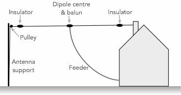
The diagram above shows a typical installation for a ham band dipole antenna. Often the supports may be a suitable point on a house and another support in the garden. On the house it can be possible to attach the dipole to the chimney, or other high point. Then another support may be a pole or even a tree. There even may be another suitable building.
It is possible to erect the antenna in many places, using the supports that are available or that can be erected. A little thought and ingenuity will provide a number of different options.
If using a tree as a support, it must be remembered that the tree will move in the wind. If the antenna wire becomes too tight as the wind moves the tree back and forth, it could break the wire. This must be taken into account, and there are several methods of overcoming this.
Dipole length
Typically coax fed dipoles are a half wavelength long as described above to give the required feed impedance.
In order that the dipole is an electrical half wavelength long, it needs to be a certain length. This is not exactly the same as that of an electrical half wavelength in free space as factors like the end effect - an effect caused by the fact the wire does not go on for ever,, the wire thickness and a host of other factors affect the length of the antenna.
It is possible to calculate the approximate length of the antenna using the formula below:
The factor "A" is largely dependent upon the length / diameter ratio and for HF antennas it is often around 0.95 to 0.98.
A table of the lengths for the HF amateur radio bands is shown below:
| Approximate Lengths for HF Ham Band Dipole Antennas | ||
|---|---|---|
| Band (MHz) | Length (Feet) | Length (metres) |
| 1.8 (160 metres) | 266 | 82.2 |
| 3.5 (80 metres) | 137 | 42.2 |
| 7.0 MHz (40 metres) | 68.5 | 21.1 |
| 10.1 (30 metres) | 47.5 | 14.7 |
| 14.00 (20 metres) | 34.3 | 10.6 |
| 18.068 | 26.6 | 8.2 |
| 21.00 (15 metres) | 22.8 | 7.04 |
| 24.89 | 19.3 | 5.94 |
| 28.00 (10 metres) | 17.1 | 5.28 |
In view of the fact that there are many variations in the calculation of the length of the antenna, and these even include the proximity to other objects and the local conditions, etc, it is always best to cut the antenna slightly longer than expected, and then trim it to provide the optimum performance.
Also it may be that the dipole needs to be optimised for operation on a particular section of the band. The length will be slightly different for the best performance at the top of a band compared to the bottom of the band. Often it depends upon whether Morse of SSB operation is envisaged.
Fortunately with the addition on an antenna tuner in the radio shack, it is possible to reduce the SWR seen by the transmitter to 1:1 anywhere in the band. If no antenna tuner was used, then the level of SWR might rise to a level where the transceiver output protection could start to reduce the power level at one extreme of the band or the other.
Buying list
A few items are needed to make an HF dipole for the amateur bands. These are normally quite easy to obtain, normally for a relatively low cost.
When buying anything for the antenna it is wise to remember that the rigours of the weather will quickly take their toll on any components, so using top quality and weatherproofing where possible is always good. Driving rain, wind, sunlight UV, etc all mean that components will have to be of sufficient quality to last very long.
- Antenna wire: Obviously one of the key requirements for the antenna is the wire itself. Whilst normal insulated copper wire can be used, copper stretches very easily, and it will be found that over time the antenna lengths as a result of the strain on it.
Often hard drawn copper wire is used and this stretches far less. The copper is less flexible, but this is not an issue for an antenna installation as the wire does not need to flex very much.
Insulators: It is good practice to place insulators at either end of the antenna. As the ends of the antenna are the points at which there is maximum voltage, the potentials reached can be very large, especially if high power transmitters are used. The wire can be attached firmly to the insulators and the in turn the insulators can be attached to nylon rope.
It is wise to incorporate a pulley at the end of the antenna. In this way the antenna can be lowered and raise if alterations need to be made, or if maintenance is required.
If a tree is used as the remote anchor point, some means of strain relief is required to account for any movement if a tree is used as one of the anchor points. This can be accomplished by using a pulley and then attaching a weight to the bottom. The weight applies the strain to the antenna wire to keep it in place, but the weight is able to move up and down to accommodate the movement of the tree.
Dipole centre & balun: The centre of the dipole requires the coaxial or open-wire feeder to be connected to it. While it may be tempting to simply connect the feeder and let it take the strain, this is not particularly satisfactory when there is a long drop for the feeder – a dipole centre should be used. This will take the strain caused by the tension on the wire, thereby avoiding damage to the feeder over a period of time. Often it is possible to use an ordinary antenna insulator for this purpose.
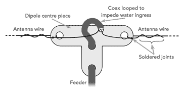
Dipole centre piece providing strain relief
Strictly speaking a balun should be used but it is often omitted especially for receiving applicationsIt should be noted that the coax is looped to prevent the ingress of water. The end of the coax should also be well sealed with sealant to provent any possibility of water entering.
Often a balun is placed at the feed point of the dipole - these are also often made to also act as dipole centres and are able to provide strain relief and a means of connecting the two radiating legs of the antenna to the coaxial feeder.
The balun is a transformer used to connect a balanced system to an unbalanced one, or vice versa - the word balun comes from Balanced to unbalanced.
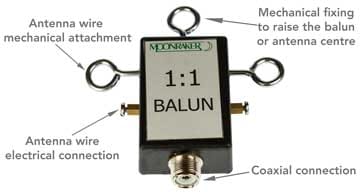
Typical HF antenna balun It is required because a dipole is a balanced antenna, i.e. neither connection is earthed, and coaxial feeder is unbalanced, having the outer braid of the feeder connected to earth. Although the antenna will operate without a balun, the use of one will prevent signal being radiated from or picked up by the braid on the feeder. This may help prevent interference being caused to nearby televisions or other forms of radio equipment. The use of a balun also ensures that the normal figure-of-eight radiation pattern is preserved and this is an advantage where directivity is important.
Baluns can be made or bought. In the case of feeding a dipole with 50-ohm coax they would normally be a 1:1 transformer, i.e. one having the same number of turns on the primary and secondary.
I thought these products may be of interest . . . . . .
These antennas and antenna components might be useful when installing your own HF antennas. They are available on AliExpress or check out my Amazon .com Storefront.

HF End Fed Wire Antenna 1‑30MHz
This end fed wire antenna uses a 1:49 balun to provide a good match. Aimed at used on the 40m, 20m, 15m, 10m, it should provide an SWR ≤ 1,5:1. Intended for low power use.

Ceramic HF Antenna Insulators
These antenna antenna insulators are ideal for use on any wire HF antenna, providing insulation at the ends where high voltages exist. The actual design is selected from the page when ordering as a variety of shapes (egg insulators to loner ribbed ones) are available to suit your needs.

500W 1:1 Waterproof HF Balun for 160m - 6m Bands
A waterproof balun and dipole centre suitable for use with a standard dipole or inverted V dipole. 1:1 turns ratio to preserve the impedance match.

WINDCAMP-Portable Dipole Antenna for Amateur Radio/h3>
This dipole covers 5 - 55MHz and includes premarked resonant points for the different amateur radio bands. Ideal for POTA & SOTA.
Check out more items you might like from our Antennas, Tuners & Meters store.
More convenient to buy from Amazon.com? Check out my Amazon Storefront.
Note: We make a small commission from any sales at no cost to you.
Feeder: The feeder for the antenna is also important. Coax cable is the obvious choice as it is easy to use and is very tolerant to the presence of nearby and this is very important when running a cable into a house. The normal impedance used is 50Ω - this is the standard used for most ham radio equipment.
It is also possible to use open wire feeder and if this is used, then it is not necessary to use a balun.
HF dipole construction practical aspects
When constructing an HF dipole for amateur radio applications, or for any application, there are a few precautions that it is wise to follow.
It is normally very easy to erect a simple dipole, but observing a few precautions may help having to redo some things, or make them better later.
Active length of antenna does not include wire looped back for securing: When mechanically securing the antenna wire to an insulator or other end point, the best way is often to take the wire through the insulator and wrap and then solder the wire around itself.

Remember when cutting the wire for the dipole to allow extra for fixing to insulators and dipole centre piece. When measuring the electrical or active length for the antenna, the section that is looped back is not included in the electrical length, and therefore the wire must be cut longer to accommodate this amount. This is in addition to the extra required so that the antenna can be pruned to the right length.
- As high as possible: As with any antenna, it is best to install the HF ham band antenna so that it is as high as possible. This will help ensure that it can provide the best performance. It is surprising the improvement that raising an antenna gives - as it starts to clear the surrounding objects that ask the signal, it will receive and radiate far better.
- Keep clear of other objects: As far as possible the HF ham band dipole antenna should be kept away from objects that could mask the signals being received and transmitted. In a domestic environment, this is not always possible, but a little planning and forethought can make the best of any installation.
- Seal coax: If coaxial cable is to be used, it is essential that the top end is sealed. If not moisture can enter the cable and the loss will increase considerably. Coaxial cable is not cheap, and even a small amount of water ingress can degrade its performance. Even when the cable has dried out, the fact that water has been in there will cause oxidation of the braid screen, etc. and this will increase the loss quite considerably.
The dipole antenna is an excellent option for many amateur radio applications especially on the HF bands like 80 metres, 40 metres, 20 metres, 15 metres and 10 metres. If erected as high as possible and in the clear, then it can provide excellent performance for remarkably little cost.
 Written by Ian Poole .
Experienced electronics engineer and author.
More Antenna & Propagation Topics:
EM waves
Radio propagation
Ionospheric propagation
Ground wave
Meteor scatter
Tropospheric propagation
Antenna basics
Cubical quad
Dipole
Discone
Ferrite rod
Log periodic antenna
Parabolic reflector antenna
Phased array antennas
Vertical antennas
Yagi
Antenna grounding
Installation guidelines
TV antennas
Coax cable
Waveguide
VSWR
Antenna baluns
MIMO
Return to Antennas & Propagation menu . . .