Trap Dipole for Multi-band HF Operation
It is often necessary to have a single dipole antenna that covers multiple bands - a trap dipole is one method of achieving this.
Home » Antennas & Propagation » this page
Dipole Antennas Include:
Dipole antenna basics
Current & voltage
Half wave dipole
Folded dipole
Short dipole
Doublet
Dipole length
Dipole feeds
Radiation pattern
Build HF ham dipole
Inverted V dipole
HF multiband fan dipole
HF multiband trap dipole
G5RV antenna
FM dipole design
There is often a need to use a single feeder and a single antenna to cover multiple frequencies or bands. One approach to solving this problem is to use what is termed a trap dipole.
Over the years a number of multi-band trap dipoles have appeared that are used for both commercial and ham radio communications applications.
The design of the trap dipole is relatively straightforward and the traps can be made to provide a high level of performance, withstanding the high voltages they are likely to need to withstand.
Trap dipole basics
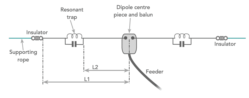
The trap dipole antenna uses a parallel resonant circuit or trap, that resonates on a particular frequency, thereby isolating a section of the antenna. This enables the inner section of the antenna to be used on the frequency where the trap resonates, and the whole antenna where it does not resonate.

The traps consist of a parallel tuned circuit, but they use components that are able to withstand the high voltages and current levels that will be present.
At its resonant frequency, the trap forms the end of the antenna, and therefore the voltage levels will be very high. Accordingly the coil former and more importantly the capacitors must be able to withstand the very high voltages present at these points. Also the traps must be able to carry the current levels needed when the trap is not at its resonant point and the whole antenna is being used.
Having a trap in the antenna means that the physical length of the full antenna is shortened to provide the required electrical length.
G8KW / W3DZZ trap dipole antena
For ham radio operation an antenna known as either the G8KW trap dipole or the W3DZZ trap dipole has gained significant popularity for HF radio communications. It provides coverage of 80 metres, 40 metres, 20 metres, 15 metres and 10 metres.
Apparently the idea of a placing a parallel tuned circuit into an antenna to make a two band antenna was first devised by Rowley Shears G8KW when he worked in the Royal Signals of the British Army in World War 2, and the concept was used in a number military radio communications installations.
The G8KW / W3DZZ trap dipole has a trap tuned to 7.1 MHz. This provides a high impedance to signals on the 40 metre and hence isolates the centre section of the antenna at this frequency. Accordingly the centre section of the antenna forms a half wave dipole for the 40 metre band. The section beyond the trap has very little effect ont he 40 metre band performance.

In practice it is found that the length between the two traps is not as critical as might be expected - the parallel tuned trap seems to reduce sensitivity of the antenna to the length between these two points.
On the 80 metre band, the antenna operates as a half wave dipole using the full length of the antenna. Operating below the resonant frequency of the traps, these become inductive and have the effect of reducing the physical length of the antenna needed to give the electrical half wavelength.
It is possible to trim the length of the outer wire of the G8KW / W3DZZ antenna to tune it to resonance of the required point in the 80 metre band.
The antenna uses additional fortuitous resonances of the full length of the antenna for operation on 20 metres, 15 metres and 10 metres. These occur as a result of the effect of the capacitors in the traps of the W3DZZ dipole antenna.
Like all multi-band antennas, there are some compromises to be made. The trap dipole approach has many advantages, although when trying to make it operate on a large number of bands like the G8KW / W3DZZ trap dipole, operation on all the pre-WARC 79 bands, the VSWR will be high on some bands and it is necessary to use an ATU to ensure that transmitter sees a suitable impedance match.
 Written by Ian Poole .
Experienced electronics engineer and author.
More Antenna & Propagation Topics:
EM waves
Radio propagation
Ionospheric propagation
Ground wave
Meteor scatter
Tropospheric propagation
Antenna basics
Cubical quad
Dipole
Discone
Ferrite rod
Log periodic antenna
Parabolic reflector antenna
Phased array antennas
Vertical antennas
Yagi
Antenna grounding
Installation guidelines
TV antennas
Coax cable
Waveguide
VSWR
Antenna baluns
MIMO
Return to Antennas & Propagation menu . . .


