
Dipole Antenna Feeders & Feed Impedance
Knowing how to properly feed a dipole antenna can improve its performance and reduce unwanted effects.
Home » Antennas & Propagation » this page
Dipole Antennas Include:
Dipole antenna basics
Current & voltage
Half wave dipole
Folded dipole
Short dipole
Doublet
Dipole length
Dipole feeds
Radiation pattern
Build HF ham dipole
Inverted V dipole
HF multiband fan dipole
HF multiband trap dipole
G5RV antenna
FM dipole design
When using a dipole antenna as with any other form of antenna, the feed impedance and a knowledge of the best way to feed it are of particular importance.
To ensure the optimum transfer of energy from the feeder, or source / load, the dipole antenna feed impedance should be the same as that of the source or load.
By matching the dipole feed impedance or dipole characteristic impedance to the source or load, the antenna is able to operate to its maximum efficiency.
In order to ensure that impedance matching is maintained there are several ways in which a dipole can be fed by its feeder.
Dipole feed impedance basics
The dipole feed impedance is determined by the ratio of the voltage and the current at the feed point – it is simply calculated using Ohm’s Law.
Although a dipole can be fed at any point, it is normal for the feed point to be at the middle of the dipole. This is the current maximum and voltage minimum point. This gives a low impedance for the dipole as can be assumed from Ohm's Law (V / I = R). This is far easier to accommodate than a high impedance feed impedance where very high voltages may be present when transmitting with even modest power levels.
Although the most common for of dipole is the half wave dipole, others can be multiples of a half wavelength. It is therefore possible to feed the dipole at any one of these voltage minimum or current maximum points which occur at a point that is a quarter wavelength from the end, and then at half wavelength intervals. As resonant dipoles are multiple of a half wavelength, this means that the most common point is still at the centre point of the antenna.

The dipole characteristic impedance is made up from two constituents:
- Loss resistance: The loss resistance results from the resistive or Ohmic losses within the radiating element, i.e. the dipole. In many cases the dipole loss resistance is ignored as it may be low. To ensure that it is low, sufficiently thick cable or piping should be used, and the metal should have a low resistance. Skin effects may also need to be considered.
- Radiation resistance: The radiation resistance is the element of the dipole antenna impedance that results from the power being radiated as an electromagnetic wave – in terms of the power loss, this can be seen by the load as power being dissipated by a resistor. The aim of any antenna is to radiate or "dissipate" as much power in this way as possible.
As with any RF antenna, the feed impedance of a dipole antenna is dependent upon a variety of factors including the length, the feed position, the environment and the like. A half wave centre fed dipole antenna in free space has an radiation impedance of 73 Ω, making it ideal to feed with 75 ohm feeder.
In reality, for all real applications, the proximity of the earth and other objects means that the figure of 73Ω is rarely seen. Typically the more common 50Ω coax is used for dipoles, especially those used for commercial radio communications application - 75Ω coax is used kore widely for domestic radio and television reception.
Factors that alter the dipole feed impedance
Although the standard feed impedance of a dipole is 73Ω (73.1Ω to be more exact) this value is rarely seen as the impedance is changed by a number of different factors.
One of the major factors affecting dipoles used n the HF bands can be the proximity of the ground.
For dipoles radiating at any frequency, if it forms the radiating element for a more complicated form of RF antenna, then elements of the antenna will have an effect. This normally lowers the impedance,. It can fall to values of 10 Ω or even less. Thus it is necessary to ensure a good match is maintained with the feeder.
Dipole height above ground
For larger dipole antennas like those used for frequencies below about 30 to 50 MHz, the height above ground can be a major influence on the feed impedance.
At these frequencies the distance between the antenna and the ground may be only a wavelength or two in many instances. At these sorts of heights, the ground can have a major influence on the impedance, especially when the antenna is mounted horizontally as is often the case.
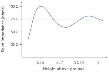
As can be seen from the impedance variation plot, the largest swings of impedance are seen when the dipole antenna is closest to the ground. It then closes in on the free space value. This means that the actual value for many HF dipoles will be relatively low as it is not possible to raise them very high in many cases. Feeding with 50Ω coaxial feeder is often a good compromise.
For VHF / UHF dipoles, it is possible to raise them much higher, although mounting poles and masts may interact to reduce the impedance. Also dipoles are not often used on their own as they are often incorporated into antennas like the Yagi.
Feeders for a dipole antenna
As the dipole antenna is a balanced antenna, a balanced feeder would be the natural choice to use to feed it. Whilst balanced open wire feeder offers very low levels of loss, and is ideal from many respects it is rarely used. There are two main reasons for this:
Unbalanced and suffers loss in buildings: balanced feeder consists of two wires, spaced apart, often as a flat wire with a plastic spacer, or two parallel wires with spacers at intervals to maintain the spacing. The issue is that this form of feeder is ideal when in pen space, but it is difficult to run it within a building, i.e. home, radio room, etc. It is for this reason that coaxial cable, which is unbalanced is more convenient to use.
Generally only used at HF: Balanced feeder tends to be used only at HF. The spacing between the parallel wires needs to be small in terms of a wavelength, and as frequencies rise, this can be an issue in some instances. Again, coaxial cable is more convenient for use, especially at very high frequencies.
The use of coaxial cable is far more common in view of its convenience and performance when operating with close by objects, or when being routed through walls and around rooms, etc.
However to use coaxial cable a transition between balanced and unbalanced is required. This is typically achieved using an item called a balun: balanced to unbalanced.If a balun is not present, RF will be present on the outer of the coax and this can mean that the coax will radiate or pick up signals. This can lead to interference from appliances in the building being picked up, or interference caused by the transmitter.
A balun is a simple item and is often a simple transformer (typically for this application it will be 1:1) or it can be implemented by placing a ferrite over the outer of the coax, to prevent signals travelling down the outer of the coax, or simply coiling a few turns of the coaxial cable next to the antenna.
Note on antenna baluns:
Baluns are used with many antennas and their feed systems to change from a balanced to an unbalanced system, or vice versa. They can take many forms and used in many antenna systems.
Read more about Antenna baluns.
The dipole antenna can perform particularly well at all frequencies, but in order to provide the best performance, the feed arrangements need to be managed properly. Feeder with the required impedance and properties, and also the balanced and unbalanced characteristics of different elements of the whole radio communications system.
 Written by Ian Poole .
Experienced electronics engineer and author.
More Antenna & Propagation Topics:
EM waves
Radio propagation
Ionospheric propagation
Ground wave
Meteor scatter
Tropospheric propagation
Antenna basics
Cubical quad
Dipole
Discone
Ferrite rod
Log periodic antenna
Parabolic reflector antenna
Phased array antennas
Vertical antennas
Yagi
Antenna grounding
Installation guidelines
TV antennas
Coax cable
Waveguide
VSWR
Antenna baluns
MIMO
Return to Antennas & Propagation menu . . .


