The inverted V dipole can form an effective antenna system for use on the HF amateur radio bands, or for other applications in many circumstances.
The advantage of the inverted V is that it only requires one high support whilst still achieving a high level of performance - the difference between an inverted V with its centre at the same height as a horizontal dipole is very marginal, and in most instances the difference in performance may not be detectable.
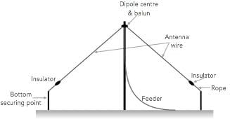
Basic inverted V dipole antenna concept
Normally the inverted V dipole is used for HF operation as the advantages of the single support are apparent on these frequencies.
In view of its need for only one high support, it makes an ideal antenna solution for many amateur radio and other stations, and even though single band options are often seen, the principle can also be adopted for mult-band antennas as well.
What is an inverted V dipole
As the name implies an inverted V dipole is a form of dipole that is in the form of a V which has been inverted. Instead of having two main supports - one for either end, both of which need to be as high as possible, the inverted V uses its main high support in the middle, having with ends having lower supports or anchorage points.
The inverted V dipole antenna has a number of advantages. One is that the maximum radiation from any antenna is from the points of high RF current, and a half-wave dipole has this maximum at its centre and for a few feet on either side of the feeder connections. Therefore it is best to make the centre of the dipole as high as possible.
If it is only possible to have one high support, an inverted-V arrangement is obviously ideal. In this way it is possible to use one fairly high mast in the centre of a garden or plot in locations where the erection of a pair of similar supports with their attendant guy wires would be difficult.
A roof-mounted or chimney-mounted mast may also serve as the centre support for a ‘V’, and the two ends of the dipole can then drop down on either side of a house or bungalow roof. Such chimney mounting will allow the feeder to be dropped to the shack quite easily if it is located in the house.
However, when using an antenna attached to a house or living area, beware of the levels of electromagnetic radiation if transmitters are used. There is a growing awareness of electromagnetic radiation, and these need to be minimised for any living area.
Inverted V dipole performance
Although an inverted-V has its greatest degree of radiation at right angles to the axis of the antenna, its radiation pattern is more omnidirectional than that of a horizontal dipole as a result of the fact that the legs are angled downwards.
The inverted-V has an excellent reputation for long distance communication on the lower-frequency amateur bands where the installation of large verticals or high horizontal dipoles is not practicable.
As an example, the inverted V dipole performance very well at low frequencies and will give good results on the 3.5MHz ham radio band when the mast is only about 14 metres or 45 feet high. This makes it a very attractive proposition for many amateur radio stations.
Similarly inverted V dipole antennas will perform well for other HF bands although they are not normally seen for frequencies above 30 MHz.
Building an inverted V dipole for amateur radio
Building an inverted V dipole is very much like that of a standard dipole. There are several elements to the installation and erection of the inverted V dipole.
Mast: One major requirement for the inverted V dipole installation is the mast. This should be robust and firmly mounted into the ground. If it is metal construction it is suggested that a good earth connection is provided.
It is also wise to install a pulley at the top to of the mast to enable easy hoisting of the inverted V dipole antenna. It is also of great benefit if ay changes need to be made or any maintenance undertaken.
End anchor points: When building an inverted V dipole and erecting it, the anchor points for the two ends should be considered. These must be located so that they do not posed a hazard to anyone in the area. They should also be located so that the antenna wire ends are out of reach. In addition to this the inverted V dipole anchor points should enable the wires to subtend an angle greater than 90° at the top centre point.
Antenna wire: The antenna wire should be of suitable quality for use externally. Ideally hard-drawn copper wire so it does not stretch, it can be single or multi-stranded.
Dipole centre: Like any dipole there needs to be a centre piece. The centre of the dipole requires the coaxial or open-wire feeder to be connected to it and whilst it may be tempting to simply connect the feeder and let it take the strain, this is not particularly satisfactory when there is a long drop for the feeder – a dipole centre should be used. This will take the strain caused by the tension on the wire, thereby avoiding damage to the feeder over a period of time.
Dipole centre piece providing strain relief Strictly speaking a balun should be used but it is often omitted especially for receiving applications
The dipole centre will also provide a means of attaching a rope to enable the pulley system to hoist the antenna centre. A good quality centre should be used wherever possible.
it is also worth noting that the end of the feeder is looped so that water is less likely enter the feeder. It is also worth ensuring the end of the feeder is well sealed with sealant.
Although baluns are often omitted from balanced antennas, these should be used if at all possible to prevent unwanted RF tracking back along the feeder, etc. Many companies manufacture baluns that also act as dipole centres.
Antenna insulators: It is always best to use insulators at the end of the antenna wire. As the ends are points of voltage maximum, insulators enable the voltages to be properly managed without breaking down. If polypropylene rope is only used, then this can hold moisture and break down.
Although insulators become wet in the rain, they will not hold the dampness for as long. They also provide a reliable way in which to terminate the antenna.
I thought these products may be of interest . . . . . .
These antennas and antenna components might be useful when installing your own HF antennas. They are available on AliExpress or check out my Amazon .com Storefront.
HF End Fed Wire Antenna 1‑30MHz
This end fed wire antenna uses a 1:49 balun to provide a good match. Aimed at used on the 40m, 20m, 15m, 10m, it should provide an SWR ≤ 1,5:1. Intended for low power use.
These antenna antenna insulators are ideal for use on any wire HF antenna, providing insulation at the ends where high voltages exist. The actual design is selected from the page when ordering as a variety of shapes (egg insulators to loner ribbed ones) are available to suit your needs.
Note: We make a small commission from any sales at no cost to you.
Inverted V dipole installation considerations
When considering erecting an inverted V dipole there are a number of considerations that should be kept in mind when its is being planned
Angle between dipole legs: The angle between the sloping wires must be at least 90° and preferably 120° or more. This angle dictates the centre support height as well as the length of ground needed to accommodate the antenna. Angle between dipole legs should be at least 90° and preferably around 120°.
For example, when designed for the 3.5MHz band an inverted-V will need a centre support at least 14m (45ft) high and a garden length of around 34m (110ft). By contrast, a horizontal dipole needs at least 40m of garden and that neglects to take into account guys to the rear of the end support masts. Again, the inverted-V is ideal for portable operation because one for operation on 20m (14MHz) only needs a lightweight 5m (15ft) pole to hold up its centre.
Dimensions need adjusting: The sloping of the dipole wires causes a reduction of the resonant frequency for a given dipole length, so about 5% must be subtracted from standard dipole dimensions. However as with an ordinary dipole it is always best to start with the inverted V a bit too log and trim it to operate with its best performance in the areas of the band most used. Also remember that the same amount must be trimmed from each end so that the dipole remains centre fed and there is not an imbalance.
Length measurement: Remember when cutting he antenna wire, that the electrical length is measured from the centre of the antenna dipole centre piece to the furthest extremity of the wire. Remember when cutting the wire for the dipole to allow extra for fixing to insulators and dipole centre piece.
Any wire used to fold back around the insulator does not contribute to the electrical length, but needs to be considered when cutting the physical wire length. An allowance also needs to be made for the dipole centre piece as well.
Radiation resistance: A further consequence arising from sloping the dipole wires is a change in its radiation resistance. The centre feed impedance of the inverted V dipole falls from the nominal 75 ohms of a horizontal dipole to just 50 ohms. This of course is ideal for matching the antenna to standard 50 ohm impedance coaxial cable.
Bandwidth: An inverted-V dipole antenna has a higher Q than a simple dipole so it tends to have a narrower bandwidth.
Keep inverted V dipole ends out of reach: It is not recommended that the ends of an inverted-V are allowed closer to the ground than about 3 metres or about 10 feet, even on the higher-frequency bands, because there can be a possible danger to people and especially children or animals touching the wire ends which will be at a high RF potential when energised. The effects, although not likely to prove lethal, nevertheless could result in a nasty shock or RF burn, and it seems unlikely that an insurance company would look kindly at any claims resulting from such an accident.
Coaxial feed is recommended with an inverted-V, and the low-loss heavier varieties of cable can be used to advantage, for there are no sag problems when the feeder is fastened up at the top and also down the length of the mast. The feeder will impose no strain upon the antenna or the soldered connections at its feed point. As with an ordinary horizontal dipole, a balun may be used, although they may operate satisfactorily without one.
Written by Ian Poole . Experienced electronics engineer and author.
Fact of the day: It was on 30th June 1905 that Albert Einstein published his article entitled "On the Electrodynamics of Moving Bodies" in which he introduced the idea of relativity.
Quote:The biggest disease today is not leprosy or tuberculosis, but rather the feeling of being unwanted, uncared for and deserted by everybody. Mother Teresa (1910 - 1997) Albanian missionary


 Written by Ian Poole .