
Make an FM Dipole Antenna Design
Details of a simple to construct DIY FM dipole antenna design that can be built easily and used for indoor reception of broadcast FM signals.
Home » Antennas & Propagation » this page
Dipole Antennas Include:
Dipole antenna basics
Current & voltage
Half wave dipole
Folded dipole
Short dipole
Doublet
Dipole length
Dipole feeds
Radiation pattern
Build HF ham dipole
Inverted V dipole
HF multiband fan dipole
HF multiband trap dipole
G5RV antenna
FM dipole design
One area in which dipole antennas are often used is for the reception of VHF FM broadcasts. Many Hi-Fi tuners and other radios have input sockets that will accept the input from a coaxial feeder, and where no external antenna is used, a dipole antenna can provide an excellent solution.
The FM dipole antenna is most likely to provide greatly improved reception over many other improvised solutions that may be used.
It is quite easy to make a simple DIY FM dipole antenna. They can be made in a variety of ways, and for minimal cost. They may prove to be the ideal solution for an internal FM antenna, possibly in the attic or roof space, or they may be used when a temporary antenna is needed.
If they are to be used for internal use, then there is no need to use expensive materials to ensure they are not affected by the weather. Instead for internal use the DIY VHF FM dipole can be made from commonly available materials and therefore the cost is likely to be minimal. It may even be possible to make a simple FM dipole using items that may already be in a junk box, or in a workshop or garage.
Dipole antenna basics
The dipole antenna consists of two poles or parts. For a half wave dipole each leg of the dipole will be an electrical quarter wavelength long.
The length of the dipole is determined by the frequency of operation. The FM broadcast band extends from 87.5 MHz up to 108 MHz. This is quite a wide bandwidth to be covered by a resonant antenna such as the dipole antenna, but as it is only used for reception the performance at the band edges is not as important as if it were to be used for transmitting.
The basic design for the FM dipole antenna is shown below.

In the diagram each leg of the dipole antenna is joined to the feeder. This can either be open wire / twin feeder, or coax can be used. Strictly speaking a balun should be used when coax or coaxial cable is used. This is because coax is what is termed an unbalanced feeder, i.e. the outer shield is connected to earth and the antenna is balanced. However for this application, no noticeable degradation should be seen and the VHF FM dipole antenna should operate quite satisfactorily without one. In this case the inner conductor of the coax is connected to one leg of the dipole and the outer conductor (braid) of the coax is connected to the other leg of the dipole antenna.
How to make the simple DIY FM dipole antenna design
To make the simple DIY FM dipole antenna, only a few items are needed. Typically these will be:
- Twin flex - twin mains flex is idea but we used some old speaker flex.
- Tie wrap - to secure the centre of the dipole and prevent the flex opening out beyond what is needed.
- String or twine to secure the ends of the dipole to relevant fixing points (if required).
- Connectors - if it is to be connected to coaxial cable.
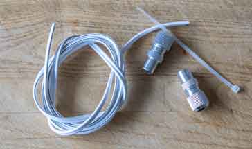
One advantage of using mains flex is that when used as a feeder for radio frequency signals this type of wire is a reasonably close approximation to 75 ohm twin or open wire feeder. This is convenient if a reasonable length is needed. For making our FM dipole antenna, we used some cheap speaker wire.
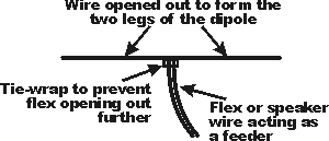
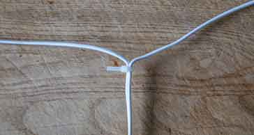
To make up the VHF FM dipole antenna, first the cable should have the two insulated wires split back away from one another and opened out. The centre should then be secured to prevent the cable opening out any further. One method of doing this is to use a tie wrap such as those available from most electronics components stockists. The length of wire which has not been split can then be used as the feeder for the antenna.
The overall length for the antenna should be about 150 cms, i.e. each leg should be 75 cms. This length should make the resonant frequency fall slightly in the lower half of the FM broadcast band, but often the more popular stations may be found in this region. If the resonant frequency is required to be higher then the antenna can be shortened slightly.
It is quite easy to calculate the length from one of the following equations:
Sometimes the equations vary a little in the constants used, as this depends on a variety of factors including the wire used, environment, frequency and the like. However it is a very good starting point and certainly good enough for making the FM dipole antenna.
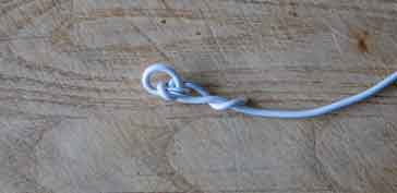
The ends of the wire can be knotted as shown to enable it to be attached to some twine or string to set it up on a loft space, etc. If this is done, the length should be taken to the extremity of the wire and any wire that is part of the knot or doubled back should not be included in the length. The knotting of the wire will add some inductance to the end of the wire, possibly making it a little long, but it should be fine for reception.
As we already had some coax cable installed around the house, our antenna was connected to a coax connector, and a mating version was attached to the coax cable. It is noting that twin feeder, such as that formed by the flex does not perform well when routed for long lengths through a house and signal losses will rise - better to use coax as this is not affected in the same way.
When installing the antenna, as far as is possible in a roof space, the antenna should away from metal objects as this will reduce the signal levels. In particular the ends of the antenna are more sensitive to nearby metal objects.
We strung our antenna up in the loft or roof space. As many VHF FM stations use vertical polarisation these days, we mounted the dipole in a vertical fashion: one end attached to a convenient nail in the wooden constriction of the roof, and the other end held down by a weight. The coax was lead away at right angles - as much as you can in these circumstances!
How to make a VHF FM folded dipole antenna
Many VHF FM hi-fi tuners have a 300 ohm input as well as the standard 75 ohm one. This input will normally have screw terminals although they will sometimes have a special 300 ohm connector. This input is ideal for use with a VHF FM folded dipole antenna which can be made up very simply. It requires only the use of a length of 300 ohm ribbon cable (not the computer multi-stranded ribbon cable) which can be bought from most electronic component stockists.
The first stage is to cut a length slightly longer than that required for the dipole element. At either end the centre plastic should be cut back and the remaining wire on either side stripped and joined together. This should be done making sure that the overall length of the element is correct.
The next stage is to cut the bottom wire in the centre. The wires should be stripped back so that a second length of ribbon can be attached. This can be made any suitable length, bearing in mind that it is likely to introduce a reasonable amount of loss if it is run within the house close to other objects. This enables the 300 ribbon to be used as feeder to be connected. This may be any suitable length.
This cheap and easy VHF FM dipole antenna is suitable for areas with high signal strengths, or it may be used as a temporary measure. The 300 ribbon cable is generally clear and can be hidden quite easily. Often this type of aerial can be fixed behind a curtain rail or a large piece of furniture.
A dipole antenna is often an ideal solution for an antenna for receiving VHF FM broadcasts. The FM dipole antenna can be a cheap and effective solution, and they can be made in a variety of forms - only two ideas are given above, but it is possible to make a VHF FM dipole antenna in many more ways according to what may be available and what the requirements are.
 Written by Ian Poole .
Experienced electronics engineer and author.
More Antenna & Propagation Topics:
EM waves
Radio propagation
Ionospheric propagation
Ground wave
Meteor scatter
Tropospheric propagation
Antenna basics
Cubical quad
Dipole
Discone
Ferrite rod
Log periodic antenna
Parabolic reflector antenna
Phased array antennas
Vertical antennas
Yagi
Antenna grounding
Installation guidelines
TV antennas
Coax cable
Waveguide
VSWR
Antenna baluns
MIMO
Return to Antennas & Propagation menu . . .


