HF Multi-band Fan Dipole Antenna
The 'Fan' dipole approach using a number of parallel dipoles of different lengths fed from the same feeder and from the same point provides a multi-band capability for a variety of radio communications applications.
Home » Antennas & Propagation » this page
Dipole Antennas Include:
Dipole antenna basics
Current & voltage
Half wave dipole
Folded dipole
Short dipole
Doublet
Dipole length
Dipole feeds
Radiation pattern
Build HF ham dipole
Inverted V dipole
HF multiband fan dipole
HF multiband trap dipole
G5RV antenna
FM dipole design
One relatively easy method of creating a multi-band dipole is to have several individual dipoles fed from the same point on one feeder.
This can be achieved using wires running parallel to each other, or as a fan emanating from the centre point. As a result, these dipoles are often called fan dipoles or fan multi-band dipoles.
Each dipole is resonant on its own frequency and will radiate as a resonant dipole for its own frequency, making this an easy way to provide a multi-band capability that enables a number of different bands to be covered using a single feeder.
These fan or parallel dipole antennas provide multi-frequency or multi-band operation that is used for a variety of commercial radio communications applications as well as for ham radio where they can allow operation on multiple bands using a single feeder.
Often it is very useful to have a multiband dipole as it saves on space and means that a number of bands can be used whilst only one feeder is required. This can be a benefit for many types of radio communication station, and especially ham radio operations.
Using a fan dipole is an easy way of having a multi-band antenna, otherwise it might be necessary to have a series of different antennas in different positions. That said, there are other options for multiband antennas which could also be adopted.
Operation of HF multiband fan dipole
The way in which the HF multi-band fan dipole operates is that each dipole presents a low impedance at the feed point at its resonant frequency. As the frequency moves away from the resonant frequency of one dipole, its impedance increases and it does not absorb power.
Then as the frequency comes to the resonant frequency of another dipole on the overall antenna, the impedance falls and this next dipole element will take power from the feeder.
In this way, the multi-band fan dipole will appear to have a number of resonant frequencies, each corresponding to the resonant frequency of the different dipoles.
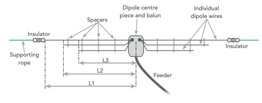
In the case of the fan dipole above, the length L1 is a quarter wavelength at the lowest frequency band, L2 the next one up, and finally L3 is a quarter wavelength at the highest band.
When designing a fan dipole, care should be taken to ensure that the one dipole resonant frequency does not correspond to the third fifth, etc harmonic of another dipole as both will have a low impedance at this point.
Implementations of the fan dipole
Although the theoretical concept of the multi-band fan dipole is quite straightforward, there are a number of ways in which it can be implemented.
If the antenna is set up as a set of parallel dipoles, then the dipole for the lowest frequency will tend to carry the weight of all the other dipoles and this can causes the whole antenna to sag.
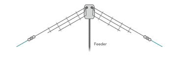
To reduce the sag there are several approaches that can be taken. This first is to reduce the number of additional dipoles added to reduce the weight, and another is to implement the parallel dipole antenna as an inverted V as this helps reduce the sag quite considerably.
It is also possible to use a more heavy duty hard drawn copper wire for the longest dipole which is used by the others for support. The others can be be made of lighter weight wire.
Beware though as this may have operational impacts because the thinner wire will have a different A factor for the length, it will make the dipole more narrow band, and also it may introduce power limitations.
However decisions about how to make the dipole can be made according to the requirements.
It is not necessary that all the wires run in parallel making a parallel wire version of the fan dipole. It is also possible to take the different dipole wires away from the feeder in different directions, fanning them out as required. When this approach is taken it is necessary to have a number of different anchor points - one for each end of each dipole .
When this approach is adopted, it is quite common to have the different wires, fanning out almost as a cone, creating a number of different inverted V dipoles, but all fed from the same feeder. It is also possible to have these wires horizontal as well, although finding sufficient anchor points may not be so easy.
I thought these products may be of interest . . . . . .
These antennas and antenna components might be useful when installing your own HF antennas. They are available on AliExpress or check out my Amazon .com Storefront.

HF End Fed Wire Antenna 1‑30MHz
This end fed wire antenna uses a 1:49 balun to provide a good match. Aimed at used on the 40m, 20m, 15m, 10m, it should provide an SWR ≤ 1,5:1. Intended for low power use.

Ceramic HF Antenna Insulators
These antenna antenna insulators are ideal for use on any wire HF antenna, providing insulation at the ends where high voltages exist. The actual design is selected from the page when ordering as a variety of shapes (egg insulators to loner ribbed ones) are available to suit your needs.

500W 1:1 Waterproof HF Balun for 160m - 6m Bands
A waterproof balun and dipole centre suitable for use with a standard dipole or inverted V dipole. 1:1 turns ratio to preserve the impedance match.

WINDCAMP-Portable Dipole Antenna for Amateur Radio/h3>
This dipole covers 5 - 55MHz and includes premarked resonant points for the different amateur radio bands. Ideal for POTA & SOTA.
Check out more items you might like from our Antennas, Tuners & Meters store.
More convenient to buy from Amazon.com? Check out my Amazon Storefront.
Note: We make a small commission from any sales at no cost to you.
However this solution is particularly applicable when a single central pole or mast is available to provide a high centre point which will enable the areas of the antenna that give the main radiation to be as high as possible and hence radiate the best signal.
It is also worth remembering that it is always good to use a balun to convert the unbalanced feeder to the balanced regime of the antenna itself. This will help ensure the correct operation of the antenna and it will minimise pickup and radiation fromt he outer of the coax.
It is also helpful to use a proper high quality insulator at the end off the dipole as shown in the diagram. If just polypropylen rope is used then this retains wated withinth e construction of the rope when it is wet. An insulator will dry out much faster. It will also give a much better and more reliable mechanical termination and fixing for the wire.
Determining the lengths of the fan dipole
Each of the halves of the dipoles is an electrical quarter wavelength long - the two halves giving a total of a half wavelength. The feed is in the centre where the current is highest and the voltage lowest and this gives a convenient low feed impedance for the antenna.
A good starting point for calculating the length of the various sections is the standard dipole length calculation equations. However be aware that the actual lengths for resonance can be longer than the calculated lengths.
The different elements of the antenna can affect each other. In view of this, it is always best to add a little extra length and be prepared to cut it back or 'prune' the lengths to get the required VSWR, etc and thereby enabling successful radio communications performance.
In view of the effect that the different dipoles have on each other, adjusting the length can be difficult, especially if the dipole has many sections for different bands. Often, two or three dipoles connected to the same feeder can give an antenna that can be reasonably adjusted. Adding further dipoles can make the job of accurately adjusting the different dipoles to length exceedingly difficult.
It is found that not only can the length of the dipoles be sometimes longer that expected by a reasonable margin, but also the length adjustment of one affects al of the others, so by the time all have been adjusted, the first one needs readjustment and so on.
Practical tips
As with any form or radio antenna there are a few practical hints and tips that are worth considering before embarking on designing and installing an HF fan antenna.
Make longest wire stronger: For fan dipoles where the different elements for the different bands are run parallel to one another, ensure that the longest element which carries the weight of all the others is strong enough. The other wires can be amde a bit thinner, but if they are too thin, then they themselves will not be strong enough and also their bandwidth will be reduced.
Don't have too many dipoles: It is wise not to put too many dipoles on the same feeder. They will all interact with each other slightly, especially if the dipoles run in parallel with each other, and if there are too many then the antenna becomes very difficult to adjust to resonance.
Keep end points out of reach: It is important to keep te end points reasonably high. This is important if children are around, and also it is necessary to ensure that the levels of electromagnetic radion are not high if anyone approaches the ends, or any part of the antenna for that matter.
Use a balun: As the dipoles are balanced and coaxial feeder which is normally used to feed the antenna is unbalanced, it is necessary to ensure that there is a proper balanced to unbalanced transition - a balun. This will prevent RF radiating from the outer conductor of the coaxial feeder picking up more interference for receiving or giving rise to more interference when transmitting. It will also distort the radiation pattern.
The multi-band fan dipole or multi-band parallel dipole provides a very neat solution for an antenna with multiple band capability. These dipoles are used for many radio communications applications and can provide a very neat and easy to implement solution for a multi-band dipole.
One of the keys to the successful implementation of these antennas is not to be too greedy and want to add too many bands. My experience has shown that two or possibly three band versions work very well and can provide excellent performance for some favourite bands.
 Written by Ian Poole .
Experienced electronics engineer and author.
More Antenna & Propagation Topics:
EM waves
Radio propagation
Ionospheric propagation
Ground wave
Meteor scatter
Tropospheric propagation
Antenna basics
Cubical quad
Dipole
Discone
Ferrite rod
Log periodic antenna
Parabolic reflector antenna
Phased array antennas
Vertical antennas
Yagi
Antenna grounding
Installation guidelines
TV antennas
Coax cable
Waveguide
VSWR
Antenna baluns
MIMO
Return to Antennas & Propagation menu . . .