Installing an antenna correctly is every bit as important as choosing the correct type in the first place.
The antenna installation can mean that the antenna performs to its best or to its worst. By adopting a number of key rules and guidelines the best performance can be obtained from an antenna under any given situation.
When installing an antenna, some compromises have to be made, but adopting some guidelines or hints and tips will enable the performance to be optimised for a given situation.
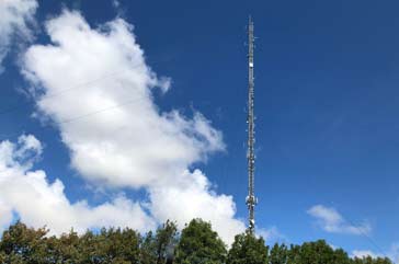
Commercial antenna systems are normally well sited and tall to provide the best coverage
Antenna installation hints & tips - guidelines
Dependent upon the type of antenna to be installed, there will be a variety of different guidelines or hints and tips that are applicable. Some antennas may be domestic television antennas, others may be CB or ham radio antennas, whilst others could be for professional applications.
Whatever the type of antenna there are many points to watch, things to think about, and items of good practice that ensure the best performance is obtained from the antenna.
There are many different areas where thought needs to be placed into the antenna
General antenna situation
One of the most important aspects of setting up any radio antenna is its location. The location of the antenna will govern many aspects of its operation, and therefore the location of the antenna must be determined along with the type of antenna to be used. A number of points associated with the antenna should be considered:
Choose a location where the radio antenna can "see" all around: In order for to operate at its best it must be able to "see" all around it. For best performance the antenna should clear the surrounding objects as much as possible
To be able to achieve this it should be kept away from nearby objects that might act as a screen. In this way the maximum amount of signal can be reach or leave the antenna without being absorbed in nearby objects.
Remember that nearby objects can "detune" an antenna: When considering the location of a radio antenna it is worth remembering that nearby objects can detune an antenna even if they do not affect the all round visibility. Nearby objects can cause an antenna to operate away from its resonant point and become less efficient. This is very important for antennas that are cut to a particular length and do not have a means of being tuned in situ. Many items can cause this to happen - metal items as well as electrical wiring are particularly bad but even trees can degrade the performance of antennas in this way. Generally the effects are noticeable within distances of a wavelength or two, the closer the object and the greater the conductivity the greater the effect.
Consider suitable points for anchoring antennas: Horizontal antennas need anchor points at either end. It is worth considering whether there are any suitable anchor points already in existence. Chimneys or other points on the house can provide one suitable point. Trees may also be located conveniently, although pulley schemes are required to enable any movement in the tree due to wind to be taken up without snapping the antenna wire. Also it may be possible to erect a pole or antenna mast and consideration can be given to this possibility and its location. Whatever option is decided upon, this must be considered at the outset.
Inside or out: In many instances the use of an internal radio antenna may have to be considered. External antennas operate better because they can be further away from objects that will introduce loss or detune the antenna. It is very difficult to estimate the amount of loss which having an antenna inside the house has. The roof or brickwork will cause the signal to be reduced, especially when it is wet. The amount of loss will also depend on the frequency. For VHF and UHF signals this will be much greater.
Use end insulators if appropriate: Wire antennas for HF, etc often need fixing to rope or other line so that they can be mounted between the fixing points: towers, hose, etc. As the high voltage point of the antenna is at the end, it is necessary to ensure that the ends are suitably insulated to prevent loss of signal. Often small insulators are used and these can be purchased easily from antenna specialist, amateur radio dealers, etc.
Antenna insulators for HF wire antennas
Antenna height
Although the height of a radio antenna could be considered under the general situation of the antenna, the height is very important and can make a marked difference to its performance. As a result the various points are considered separately.
Increasing the height of the antenna will nearly always improve its performance whether used for HF, VHF, or UHF etc.
Interference caused to ham radio stations and interference cause by them is obviously of great importance. The location of the antenna for the ham radio station can have a significant impact on both aspects of interference. As a result this should be kept in mind when choosing the location for the radio antenna.
Keep the radio antenna away from sources of interference in the house: Most houses contain many items which are very good sources of noise. Although televisions and computers are very much better nowadays, some interference is still generated particularly as many computers now have networks associated with them. Interference is also generated form a variety of other electrical items around the home. Vacuum cleaners, electric drills, electric mixers and a host of similar utensils all contribute to the level of electric noise generated. This radiates in and around the house, reducing in intensity the further away from the source one moves. As a result it is best to try to keep the antenna as far away from the house. This may not always be possible the level of interference can be minimised by keeping the antenna away from particular sources of noise.
Ham radio transmitters (or any radio transmitters for that matter) can cause interference if they are close to domestic appliances: Despite the fact that domestic equipment is very much more resilient to interference than it used to be, there is still the possibility that a ham radio transmitter can cause interference. One of the best ways of reducing the possibility of any interference is to ensure that the ham radio antenna is situated away from any other equipment. This is best achieved by keeping the antenna away from any domestic premises. Obviously the risk is less for low power transmitters, but for high power amateur radio stations this can become more of an issue, especially if directive antennas are used which could be beamed towards any domestic premises.
Antenna matching
Matching the antenna to the feeder is is particaulrly important if radio transmitters are used and they are to operate effectively with the antenna system. Naturally it is also important for receiving systems as well, but may be not quite as crucial. Radio frequency systems such as antennas, feeders, sources (i.e. transmitters) and loads (i.e. receivers) all have a characteristic impedance.
For the system to operate effectively these must match, otherwise standing waves are generated and the power transfer is reduced. To ensure that the overall system is properly matched and is operating correctly a number of measures can be introduced.
Often for domestic systems such as TV or radio installations, the relevant matching techniques will be employed to ensure this should not be a concern.
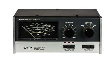
Use a VSWR meter to ensure that the radio antenna system is operating correctly: Antennas usually operate only over a relatively narrow bandwidth, and many antennas are only able to operate on a single band, and sometimes adjustment is needed to enable them to operate even at different ends of the band.
Typical VSWR meter used with a transmitter
This ensures that the antenna is matched to the feeder, and the maximum amount of power is transferred. To check whether the antenna is operating correctly a VSWR meter can be inserted in the line. By keeping one in circuit at all times the operating of the system can be monitored.
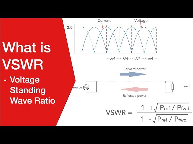
Note on Standing Wave Ratio, SWR & VSWR:
Standing waves are often associated with RF feeders, and they are generated when there is a mismatch between the feeder impedance and the load impedance. At th emismatch, power is reflected and the combined voltages and currents of the forward and reflected power form standing waves along the feeder.
Consider the use of an ATU to ensure the optimum antenna operation: In order to ensure that the antenna impedance matches that of the feeder it is often necessary to employ a matching or tuning unit between the feeder and the antenna itself.
These antenna tuning units (ATUs) are used to tune the radiating element so that its impedance matches that of the feeder so that the maximum power transfer is obtained and the level of standing waves is minimised. To be able to tune the antenna properly the ATU should be located at the antenna.
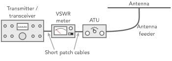
Use an ATU in the shack to reduce the level of VSWR seen by the radio transmitter output stage: High levels of standing waves can cause damage to the semiconductor output stages of radio transmitters. To protect these stages from damage, many transmitters detect the level of VSWR (voltage standing wave ratio) and reduce the output power when levels start to rise.
Incorporating an ATU into a transmitter feed system with a VSWR meter
Therefore to ensure that the transmitter can deliver its maximum power output a low level of VSWR must be present. When it is not possible to have an ATU right at the feed point of the antenna, one can be placed near the transmitter to tune the antenna feeder combination so that the VSWR seen by the transmitter is minimised. While not totally ideal it can help by allowing the transmitter to see a low level of VSWR.
Use a balun: Where balanced antennas like dipoles, or antennas that use dipole element are used with an unbalanced feeder such as coax, it is always wise to use a balun. These baluns take various forms and can even be a simply coil of the coax cable. However a balun should be implemented wherever possible to preven pick-up or radiation fromt he coaxial feeder and ensure proper operation of the dipole antenna itself.
Note on antenna baluns:
Baluns are used with many antennas and their feed systems to change from a balanced to an unbalanced system, or vice versa. They can take many forms and used in many antenna systems.
The feeder is an important part of any radio antenna. Its purpose is to ensure that the maximum amount of power reaches its destination, either radio transmitter power reaching the antenna, or incoming signals from the radio antenna reaching the receiver. Any power lost will reduce the efficiency of the whole antenna system. The feeder cost and performance considerations may have an effect on any decision made regarding the antenna, and it is therefore important.
Choose the optimum feeder for any situation: The cable type should be chosen to provide an acceptable loss at the frequencies to be used. For frequencies below 30 MHz feeder loss is normally quite low and subject to power limitations thinner coax may often be used unless long runs are required. As frequencies rise, so do the levels of loss, and thicker, lower loss varieties are needed. Although the cost can be high, an investment in a low loss cable can ensure that the overall antenna system operates to its full capability.
Consider the installation of the feeder when planning the radio antenna installation: Any feeder should be correctly installed. For example if it is coax or coaxial cable, it should not be bent too tightly beyond its minimum bend radius. If this is done damage may occur. Open wire feeder should not be run through a house as nearby objects will de-tune it and losses will rise. Any run inside a building must be kept to an absolute minimum
Suitably weatherproof any feeder if it is to be used externally: In particular, great care should be taken when using coaxial cable outside. The end of the coax should be sealed to prevent any moisture ingress. Moisture will itself cause loss as it will absorb power, and for the longer term it will give rise to corrosion which will degrade the performance of the coax.
Good earth
One good solution for many ham radio HF antenna requirements is a ground mounted vertical. These and a number of other radio antenna systems require the use of an efficient earth or ground system for it to operate satisfactorily. As the ground system is key to the operation of the radio antenna it is necessary to ensure that the ground system is satisfactory.
Ensure the ground system has a low electrical resistance: One of the major requirements for an earth or grounding system for an antenna is that it should have a low electrical resistance. This can be achieved by ensuring that there is the maximum surface area of metal in contact with the earth itself. Electrical grounding rods as well as old copper pipes can be used.
Ensure the ground system has a low RF resistance: Although good electrical conductivity for DC is required, the RF performance can be further improved by laying radials, typically a quarter wavelength long radiating out from the central ground point. If compromises have to be made, they should be laid out in the direction where optimum performance is required.
Ensure the main point for the ground system is as close to the feed point of the ground mounted antenna as possible: Antenna systems using a ground system do not operate well if the lead to the ground system is long. Accordingly the main connection for the ground system should be as close to the base of the antenna as possible.
Consider the ground conductivity: The conductivity of the ground itself should be considered when choosing a place for the ground system. Dry sandy soil gives a poor connection whereas damp fertile soil gives a much better result. If possible the earth connection should be made in a place where the earth connection will be better. This may alter the choice for the position for some vertical antennas, or it may mean that ground mounted systems may not be viable.
Note on antenna RF grounding:
Grounding an antenna can be key to its operation, particularly if it is a vertical monopole antenna where the ground forms part of the antenna.
When any radio antenna system is installed, whether for ham radio or any other purpose, safety must be one of the major considerations. Sometimes antennas are temporarily fitted up, only to fall down when the wind rises. Home-built antennas are particularly at risk, but even commercially made ones can suffer if they are not installed correctly - and sometimes even when they are. Care must be taken to ensure that there is no chance of the antenna falling and injuring someone.
A number of the key points are listed below:
One of the key safety guidelines is to keep all object as far away as possible from power lines. This includes masts, poles, antenna wires, other forms of antenna, feeders, ladders, and any tools used. Ideally keep the distance from an antenna or pole to the power line at least twice the height of the antenna or pole.
Ensure that all antennas are well constructed so that they can withstand the rigours of the weather and cannot fall on people.
Ensure that all antennas are well maintained and any issues resolved before they fall.
If climbing a tower or up a ladder, ensure that all the necessary precautions are taken. Only trained people should climb ladders and towers, etc.
Installing antennas and cabling often requires holes to be made in walls and ceilings so that feeders etc can be passed through. When drilling holes, etc take care not to drill through an electrical wire or water / gas pipe. Sensors are available that give an indication of wires and metal pipes buried in walls. These are cheap and may well prevent a disaster.
Above all an overriding sense of the safety aspects of radio antenna design and installation must be employed when installing antennas. With the weather being what it is, any risks taken are likely to result in failure before long. It is not worth taking any risks as falling antennas can cause harm to people and to property, and in any case an antenna on the ground cannot be used.
Experimenting with radio antennas can be a fascinating area or ham radio. Many ham radio enthusiasts find it a particularly rewarding element of the hobby. Also, experience gained from setting up and testing various types of radio antenna can be very useful, adding vastly to some of the basic guidelines summarised here. It can also be very rewarding when a new antenna performs particularly well, and much better than previous installations. The performance of the ham radio station can be greatly improved and this can often be seen in the results with many distant contacts being made.
Written by Ian Poole . Experienced electronics engineer and author.


 Written by Ian Poole .