Kirchoff's Current Law (First Law)
Kirchoff's Current Law is his first law of circuit analysis and states that the current flowing into and out of a node sums to zero, i.e. no charge is lost or gained.
Kirchoff's laws Includes:
Basics of Kirchoff's Laws
Kirchoff's Current Law (First Law)
Kirchoff's Voltage Law (Second Law)
Kirchoff's current law is also known as Kirchoff's first law and it is one of the key tools used in the analysis of electrical and electronic circuits.
The Current Law enables the currents flowing into and out of a node of junction to be calculated thereby enabling aspects of a circuit to be determined.
Kirchoff's Current Law definition
It is a useful first step in understanding Kirchoff's Current Law to define exactly what is says. Using this as a grounding, it is possible to build the explanations on the definition.
Kirchoff's Current Law definition:
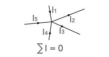
Kirchhoff’s Current Law states that the algebraic sum of all the currents at any node point or a junction of a circuit is zero.
It is possible to summarise the law by saying that for any point, junction, node, etc, the sum of all the currents entering and leaving is zero. Obviously the sign of the currents needs to be taken into account. The reason for this is that charge cannot mysteriously appear or disappear, it has to go somewhere.
The law can be easily summarised mathematically:
This equation mathematically expresses Kirchoff's Current Law. Although we have used the notation ΕIin as the currents entering the node, this would mean currents flowing into the node are positive and those outwards are negative, it is equally valid to use ΕIout, but with the signs reversed. The main observation is the currents flowing into the node have one sign, and those outwards have the opposite.
The diagram below gives a good way of thinking about the currents when they are flowing into and out of a node. Note that the negative lead for the test meter is always connected tot he "node" end of the wire in which the current is being monitored. In fact it does not matter which way round the currents are measured as long as a constant methodology is used. The signs will then indicate the sense of the current for calculating Kirchoff's Current Law.
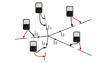
It is worth noting that to measure the current, the connection must be broken and the multimeter switched to measure current with the required range is inserted. Although there are some current probes that do not require to be inserted into the actual circuit, they are not normally available.
The equation can also be expressed in a slightly more understandable manner:
Again, a consistent notation must be used - all currents flowing into or out of the node. If the wrong sign is used for any of the currents, then this will cause the results to be totally incorrect.
The notation is even more important when undertaking more complicated electrical or electronic circuit analysis. Methodical use of a consistent notation is key to ensuring that the correct answer is achieved.
 Written by Ian Poole .
Experienced electronics engineer and author.
More Basic Electronics Concepts & Tutorials:
Voltage
Current
Power
Resistance
Capacitance
Inductance
Transformers
Decibel, dB
Kirchoff's Laws
Q, quality factor
RF noise
Waveforms
Return to Basic Electronics Concepts menu . . .