Kirchoff's Voltage Law (Second Law)
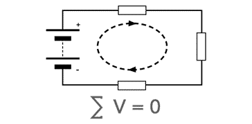
Kirchoff's Voltage Law is his second law of circuit analysis and states that the voltage around a loop sums to zero, i.e, potential generation equals potential dissipated.
Kirchoff's laws Includes:
Basics of Kirchoff's Laws
Kirchoff's Current Law (First Law)
Kirchoff's Voltage Law (Second Law)
Kirchoff's voltage law is also known as Kirchoff's second law and it is one of the key tools used in the analysis of electrical and electronic circuits.
The Voltage Law is used in a variety of areas where electrical and electronic circuit analysis is undertaken. It is one of the key techniques used in a variety of circuit analysis software tools.
Using the law, it is possible to gain insights into the analysis of a circuit that would not be possible by other means. In many respects the basis of the law: conservation of energy and conservation of charge, is straightforward, but it gives a new view of electrical and electronic circuits that is not possible using earlier views of circuits.
Kirchoff's Voltage Law definition
In order to better understand Kirchoff's Voltage Law, the first step is to look at the definition of the voltage law. Having done this, the explanations can be more easily undertaken.
Kirchoff's Voltage Law definition:
The voltage law states that the algebraic sum of the voltages in any closed path of an electrical or electronic network in any single direction is zero.
Put into electrical and electronic circuit terms, this means that in any loop in a circuit, the sum of all the potentials, where created by a source or dropped or dissipated by an electronic component, must equal zero.
This can be expressed mathematically:
In summing all the voltages around a loop, it means that the polarities must be taken into account, with the sources adding voltage and other electronic components such as resistors dropping the voltage.
Kirchoff's Voltage Law obeys the conservation of energy principle. If a probe moves around a circuit loop, there will be various sources and potential drops. These must add up to zero, because when the probe returns to the start point, it must be at the same potential as it was at the beginning.
Explanation of Kirchoff's Voltage Law
Possibly the best way to explain Kirchoff's Voltage Law is to provide a simple example. take the simple electronic circuit below consisting of a battery (voltage source) and three resistors, all in a loop.
This simple example can be used to provide a first look at how the law operates in a real scenario.

To illustrate the way Kirchoff's Second law works in this circuit we have taken a simple closed loop with three resistors and a voltage source. The figures used have been chosen to make the calculations easy and the example clearer to follow.
It is possible to measure the voltages across each component in the circuit, and then add them up. In each case the meter is applied with the polarity of the meter in the same sense according to the direction of rotation.
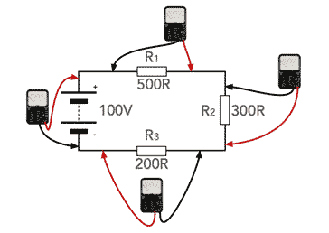
Note that the negative lead for the test meter always measures the most anticlockwise point around the component
To look at the circuit further, it is necessary to find out the total resistance. This can easily be achieved because the total resistance of resistors in series is the sum of the individual resistances. This means the overall resistance is 1000Ω.
From Ohm's Law, the current flowing is V / R = 100 / 1000 = 0.1A. It is then possible to calculate the voltages across the individual resistors from Ohm's Law using the fact the current through each resistor is 0.1A.
It is important that the sign of the voltage drop is taken correctly. It can be seen that the way in which the meters measure the voltage, with the positive lead of the meter in the most anticlockwise direction, the voltage for the battery will be positive, but the voltage drops across the resistors will be negative.
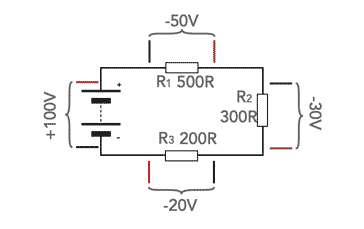
It is possible to tabulate the voltages around the circuit loop and sum them to see the overall effect.
| Voltage Summation Around the Circuit Loop |
|
|---|---|
| Circuit component | Voltage Contribution |
| 100V Battery | +100V |
| 500R resistor | -50V |
| 300R resistor | -30 V |
| 200R resistor | -20 V |
| Total | 0 V |
Although this may seem fairly basic in its concept, having used Ohm's Law to calculate the voltages around the circuit loop, it does prove that Kirchoff's Voltage Law for this circuit.
Kirchoff's Voltage Law in larger circuits
The demonstration above shows in very simple terms that Kirchoff's Voltage Law applies to a simple loop circuit. However the same principles can be applied to much more complicated circuits consisting of multiple circuit loops, etc.
It is in more complicated circuits that Kirchoff's Law comes into its own and becomes exceedingly useful. Here it can enable circuits to be analysed in detail, and it provides the basis for many electronic circuit analysis software packages.
It is worth looking at a typical example of a system with two loops in it. This gives a ore real-life form of example where there are often multiple loops. The same basic techniques that are used to solve this simpler example can be expanded for greater number of loops.

It can be seen that the electronic circuit consists of two batteries with two resistors in series with each battery and then one resistor connected to the junction of the other two resistors to ground. Although there is a limited number of electronic components, the calculations can be simplified for the example, whilst still showing the basic principles used.
Particularly when using multiple loops, it is important to ensure that the conventions for which way round the different loops, the voltages will be summed. Provided that each loop is summed correctly, the overall equations will work, but getting signs wrong can cause issues.
In the electronic circuit below, the directions have been selected and the voltages can be summed accordingly.
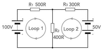
In Loop 1 the current flowing from the battery is taken as I1 and similarly, the current from the battery in Loop 2 is I1.
It is possible to create two simultaneous equations for the two loops:
By isolating the different variables and then substituting them in the other equation it is possible to calculate the currents to be:
The simultaneous equations do not yield very easy calculations always, but it can be seen that it is possible to calculate the two current levels in the circuits, noting that in the resistor R2 the current is the addition of both I1 and I1.
Although the calculations can become long winded, this is a very powerful technique for analysing electronic circuits. Even if the number of loops increases, there is still only one unknown per loop. Using computer techniques it is possible to perform circuit analysis on some large electronic circuits.
Accordingly Kirchoff's Voltage Law is a key tool in the toolbox for undertaking electronic circuit designs. Although they may not be used in their elemental form, they are likely to be incorporated into electronic circuit analysis software packages.
 Written by Ian Poole .
Experienced electronics engineer and author.
More Basic Electronics Concepts & Tutorials:
Voltage
Current
Power
Resistance
Capacitance
Inductance
Transformers
Decibel, dB
Kirchoff's Laws
Q, quality factor
RF noise
Waveforms
Return to Basic Electronics Concepts menu . . .