
Electronic Waveforms & Signals: sine, square, triangle, ramp, etc
Within electrical and electronic circuits there are many different types of waveform and signal that can be seen: sine waves, square waves, triangular, sawtooth, ramp and the like.
Electronic & Electrical Waveforms Includes:
Waveform types & basics
Sine wave
Square & rectangular waves
Triangular wave
Electrical or electronic waveforms and signals such as sine waves, square waves, triangular waveforms, ramp waveforms and the like are seen in all sorts of ways within electronics.
Waveforms are displayed on oscilloscopes and were are used to seeing these waveforms to illustrate the voltages and currents in electronic circuits.
These waveforms can have a variety of shapes as well as having a variety of properties. Not only do the plots of the waveforms look different, but they can act differently within electronic circuits.
Knowing a little about these waveforms can help in understanding electronic circuits when items of test equipment like oscilloscopes are used to display the waveforms at various points.
Video: Electronic Waveforms: sine square, rectangular, triangular, sawtooth (ramp)
The sine wave is the simplest of all electronic waveforms, consisting of a single frequency and hence when dealing with examples in circuits and the like, the sine wave is often chosen.
Waveforms like square waves, triangular waves and others all contain harmonics and this makes them more interesting from a musical viewpoint. When analyzing non-sinusoidal waveforms, it will be seen that the proportions of the different harmonics changes and it is this that changes the shapes of the waveforms.
What is an electronic waveform
There is a lot of talk about electronic waveforms and signals such as sinewaves, square waves and the like. Basically an electrical or electronic waveform is just a visual representation of typically voltage or current over time.
The x-axis or horizontal axis is the value of time, whereas the y-axis or vertical axis is the parameter that varies which is typically the voltage or current.
Often voltage is the most widely seen and displayed on test equipment such as an oscilloscope, although current can also be plotted.
The oscilloscope plots have become very commonplace, so it helps to become familiar with them so that when a waveform is viewed on an oscilloscope, it can be interpreted and understood.
When looking at waveforms, there several key aspects to a waveform:
Non-periodic: Non-periodic waveforms are those that vary but do not repeat the waveform. A good example of this is true noise because it varies randomly and does not repeat.
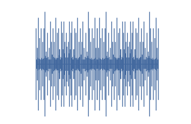
Noise as seen here on an oscilloscope is a good example of a non-periodic waveform because it does not repeat Another example might be a control signal that responds to an analogue input. It will change state according to an external random input, but it will not have a given repetition time.
Periodic: As the name indicates, a periodic waveform has a period over which it varies and then repeats itself. These are some of the waveforms that are of most interest because they can be used in a variety of ways. A sinewave, square wave, ramp, triangular waveforms and the like are all periodic waveforms
Another way in which waveforms can be categorised is according to whether they are uni-directional or bi-directional:
Uni-directional waveforms: As the name suggests, the current or voltage for these waveforms or signals remains the same, although varying. It never crosses the zero line.
Bi-directional waveforms: Waveforms that are bi-directional have current or voltage with both signs, i.e. negative and positive. The measurements or plots of these waveforms cut through the zero line. In other words they alternate from positive to negative.
When looking at any periodic waveform there are three key features that are often stated and measured whether they are sine waves, square waves, ramps, triangular waveforms of whatever form of electronic waveform:
Period: The period of a waveform or signal is the length of time for a complete cycle, i.e. from one point on the waveform to the same point as the cycle starts again.
The period is measured in seconds, although obviously the decimal multipliers or submultiples like micro (µs) and pico (ps) apply. Although remember when using formulas that this multiplier must be accounted for. The periodic time, is often denoted by the letter T.
It is worth remembering that the periodic time for a square wave is still the time for a complete "cycle," but often a pulse width, i.e. the width of a part of a pulsed waveform may be measured because the time for the width of a pulse may be needed.
Frequency: The frequency of a waveform is the number of times the waveform repeats itself within a one second. The unit of frequency used to be called cycles per second, c/s, but now the unit has been named the Hertz after Heinrich Hertz who was the first person to knowingly detect electromagnetic or radio waves.
The usual multipliers of kilo, Mega and the like are used so 1 kHz is 103 hertz, 1 MHz is 106 Hertz, Giga is 109 Hertz and so forth.
Amplitude: The amplitude of a waveform is its magnitude and for electrical or electronic circuits and applications, it is normally measured in terms of volts or amps.
Frequency and time period
The time period of a waveform or signal and its frequency are linked together. As the time period for the waveform decreases, so the frequency increases. This is because as the time period reduces it takes a shorter time for the completion of a cycle and more cycles will appear within a second.
It is possible to relate the frequency and time period in an equation.
Similarly by manipulating the equation we can see that:
Where:
f = frequency in Hz
T = time period of one cycle in seconds
As waveform frequencies often rise to thousands, millions and hundreds of millions of Hz and beyond and similarly because time periods of the waveforms fall, the standard prefixes are used to denote higher frequencies and smaller time periods.
| Prefix | Definition | Denoted | Time Period |
|---|---|---|---|
| Kilo | 103 | kHz | 1ms |
| Mega | 106 | MHz | 1µs |
| Giga | 109 | GHz | 1ns |
| Tera | 1012 | THz | 1ps |
Waveform types
There are many different types of waveform that are seen in electronic circuits. Each type of waveform has its own characteristics and is seen in different places.
The different types of electronic waveform or signal are used in different areas. Sine waves are seen in many RF circuits, whereas square waves are seen in many logic applications and ramps, sawtooth waveforms where a voltage or current may linearly ramp up to a given voltage before resetting. Each type has its own characteristics.
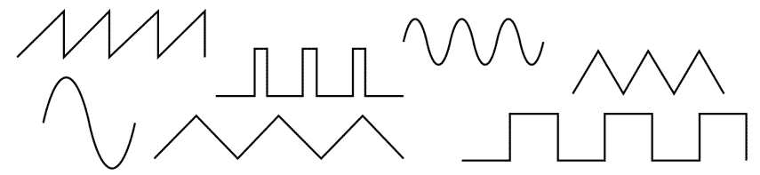
• Sine wave:
Sine waves ( and not sign waves as has been seen in some cases) are signals that oscillate smoothly either side of a central value - normally zero volts.

Sine waves can be expressed as the sine of the angle where there are 360° for each cycle or 2π radians. The sine wave follows the amplitude for any given point can be calculated using V sin(ω.t) where V is the peak voltage, ω is the angular velocity and t is the time.
• Square wave:
Square waves switch between two values. Square waves have the same amount of time in each state - they are square waves after all.

Important characteristics of a square waveform apart from the amplitude and frequency / period are the rise and fall times of the edges. These can be particularly important when driving logic circuitry.
• Rectangular waveform / pulse train:
A rectangular waveform is a square waveform but with different times within the different states. This makes the waveform have a rectangular shape rather than a square shape.
In some instances the waveform may tend to become more of a train of short pulses when the time on one state is much greater than the other.
• Triangular waveform :
A triangular waveform rises and then falls. The most common form of triangular waveform rises and then falls at the same rate, although it is possible for the rise and fall rates to be different if required.

The rise and fall are linear lines and the transition between rise and fall is near instantaneous.
• Sawtooth (ramp) waveform:
A sawtooth or ramp waveform is one which rises to its final value and then falls away with a near vertical drop. This gives a positive ramp waveform.
It is also possible to have a negative ramp where the signal slowly falls from a maximum to the low value and then rises with a near vertical slope to the maximum value again.

Ramp signals were widely used for analogue televisions where the spot scanned from one side of the screen to the other and then flew back to the beginning again. A ramp voltage was used to steadily move the spot across the screen and then the swift fall would return it tot he start of the scan again.
There are many other forms of waveform found in electronic circuits, but these are some of the more widely used.
Generating electronic waveforms & signals
It is often necessary to be able to generate waveforms for electronic circuits. Although the most widely used form of generator tended to be a sine wave oscillator, other types of generator are available that can generate a host of different types of waveforms.
There is a variety of different types of generator used for generating different waveforms.
Arbitrary waveform generator : The arbitrary waveform generator is a type of signal generator that creates very sophisticated waveforms that can be specified by the user. These waveforms can be almost any shape and can be entered in a variety of ways, even extending to specifying points on the waveform.
Audio signal generator: As the name implies this type of signal generator is used for audio applications. Signal generators such as these run over the audio range, typically from about 20 Hz to 20 kHz and more, and are often used as sine wave generators. They are often used in audio measurements of frequency response and for distortion measurements. As a result they must have a very flat response and also very low levels of harmonic distortion.
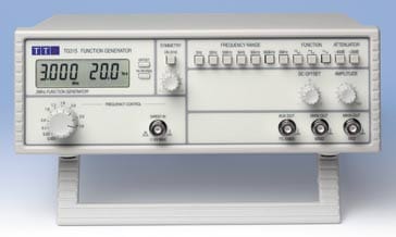
Function generator: The function generator is a type of signal generator that is used to generator simple repetitive waveforms. Typically this signal generator type will produce waveforms or functions such as sine waves, sawtooth waveforms, square and triangular waveforms.
Early function generators tended to rely on analogue oscillator circuits that produced the waveforms directly. Modern function generators may use digital signal processing techniques to generate the waveforms digitally and then convert them from the digital into an analogue format.Pulse generator: As the name suggests, the pulse generator is a form of signal generator that creates pulses. These signal generators are often in the form of logic pulse generators that can produce pulses with variable delays and some even offer variable rise and fall times.
These are some of the main types of signal generator that produce a variety of the standard types of waveform.
Note on Signal Generators:
There are many different types of signal generator, ranging from audio oscillators which often produce only sine aves, through the various forms of function generator, arbitrary waveform generator and the like that produce a variety of different types of waveform, through to RF signal generators and vector signal generators that are used for producing RF signals, often with complex RF waveforms and modulation formats.
Read more about Signal Generators.
Often these days, oscilloscopes can contain signal generators which can be used in conjunction with oscilloscope measurements, or on their own. Typically the function generator or arbitrary waveform generator will tend to match the performance of the scope. This will be particularly in terms of the frequency coverage of the signal generator.
The various types of waveform or signal are seen in many places within electronic circuits. In terms of their visualisation, they will often be seen displayed on oscilloscopes and having an understanding of the different waveform types will enable a better understanding of the circuit to be gained.
 Written by Ian Poole .
Experienced electronics engineer and author.
More Basic Electronics Concepts & Tutorials:
Voltage
Current
Power
Resistance
Capacitance
Inductance
Transformers
Decibel, dB
Kirchoff's Laws
Q, quality factor
RF noise
Waveforms
Return to Basic Electronics Concepts menu . . .


