What is a Square Wave & Rectangular Waveform
Square waves, rectangular waves and pulsed waveforms are all waveforms that have two states; high and low and they are widely used with digital circuits.
Electronic & Electrical Waveforms Includes:
Waveform types & basics
Sine wave
Square & rectangular waves
Triangular wave
Square waves are a form of periodic waveform that alternates between two states and are not sinusoidal.
In the ideal square wave the transitions between the two states are instantaneous, but in the real world this is obviously not the case and the rise and fall times are of great interest.

Although the term square wave is used for many forms of two state waveform, strictly speaking a square wave is one that is square and has equal times on either state, i.e. it has a 1:1 mark to space ratio. A rectangular waveform is a periodic two state waveform that has unequal mark to space ratio.
A pulsed waveform is one that may not be repetitive, or periodic. This could result from the pulse being generated when a certain analogue threshold is reached, or it may be carrying data, or many other reasons.
Video: Understanding Square Waves in Electronic Circuits
What does a square wave sound like
A square wave sounds much more piercing than a sine wave. This results from the fact that it has sharp edges as a result of the fast squared edges on the waveform.
The square wave is rich in harmonics and this gives it a quite interesting tone from a musical viewpoint.
Basic aspects of square waves
Square waves appear in a variety of electronic circuit designs and other areas of electronics. They are particularly prevalent in digital or logic circuits where the system deals with digital data and waveforms.
When used in a logic or digital circuit the two states are often designated as "1" and "0" corresponding to the binary digits. They may also be referred to as "HIGH" and "LOW" indicating the voltage.
The logical "1" state is the same as the "HIGH" state and "0" is the "LOW" state.
This terminology is adopted because logic circuitry normally is associated with binary numbers and signals. There are many circuits that use logic circuitry, some may be relatively simple using small logic chips, whereas others may use microprocessors or microcontrollers, etc.
As it is not always possible to determine the exact voltage, a window is generally given in electronic circuits for the high and low states.
There are many aspects of a square wave that often need to be specified.
Time period: The time period of a square wave is one of the key parameters that describes the waveform. As the main features of the square wave are the rising and falling edges, these are the key areas that are used for the markers for defining the time period. Either the measurement can be made from one rising edge to the next or one falling edge to the next.
The same trigger voltage is used one one cycle to the next in case there is any slope in the rising or falling edges. However for any measuring instrument the trigger point will be the same from one measurement to the next so this is not an issue.
Frequency: Like that of a sine wave, the frequency of a square wave is the number of times the waveform alternates in a second. The frequency used to be measured in cycles per second, but now the unit Hertz is used where one Hertz is equal to one cycle per second.
If the frequency of a square wave is known, then it is possible to calculate the time period and vice versa.
Similarly by manipulating the equation we can see that:
Where:
f = frequency in Hz
T = time period of one cycle in secondsAmplitude: The amplitude of a square wave may be specified on one of a number of ways.
Obviously it is possible to measure and specify the voltage of the waveform as a peak voltage or peak to peak. This might be used of the square wave was being used with an analogue system alongside other waveforms such as a sine wave or other waveforms.
However square waves are most widely used with digital designs for electronic systems or other logic systems. With digital designs the values for the low and high states are of interest.
Typically the low state is between 0 V and 0.4V and the high state is between 2V and the supply rail which is typically 5.0V for standard TTL. More modern logic families use much lower voltages, but the same principles hold true, although the voltages will be slightly different.
Square wave rise and fall times
One important aspect of square waves is the time it takes the wave form to rise and then fall away.
The square wave rise and fall times are often quoted. For example a the square wave from a signal generator may have a specification for its rise and fall times.
Sometimes it is necessary to measure the rise and fall times of a signal because it can affect the operation of some electronic circuit designs, especially those using digital technology.
Normally the rise time is measured as the time for the rising edge to go from 10% of the final value to 90%. Similarly the falling edge uses the same points as well.
Normally the 10% & 90% points are used, although on some occasions 5% and 95% may be used, but this is les common.

In the diagram, the 10% and 90% values are given and the times trise and tfall refer to the rise and fall times respectively.
For most logic families using digital and square waveforms the rise and fall times are likely to be specified in terms of nanoseconds.
Square wave spectrum & Fourier analysis
If the spectrum of a square wave is analysed then it will be found that it is made up from a series of harmonically related sine waves.
In fact any periodic waveform can be analysed in this way and the constituent frequencies or sine waves can be determined.
If the spectrum of a square wave is analysed it will be seen that the waveform is made up from a sine wave at the fundamental frequency, one at three times the fundamental, but at a third of the amplitude, one a the fifth harmonic, but at a fifth the amplitude and so forth. In other words it is made up from a series odd-integer harmonic frequencies.
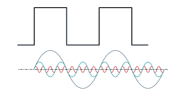
The greater the number of harmonics present, the more exact the representation. This means that if the square wave is passed through a low pass filter, then it will be distorted and the edges, rise time and the like will be inferior to that of the square wave with infinite bandwidth.
When expressed mathematically the square wave be represented by the equation below:
The actual spectrum of a square wave can be seen on this plot of the spectrum of a square wave taken from a test instrument.
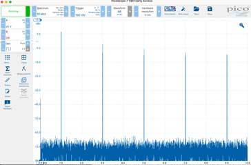
On the diagram, the fundamental will be seen towards the left of the scan - note that the zero frequency line is right on the left of the scan. The harmonics can then be seen at the odd multiples of the fundamental.
It must be remembered that the amplitude scale is logarithmic, but it can be seen that the harmonics are at 3, 5, 7 and further odd multiples of the fundamental and that they are reducing in amplitude with increasing frequency.
It can also be seen that the even multiples are not present as a square wave only consists of the odd integer harmonics.
Square waves, rectangular waves and pulsed waveforms are seen in a huge number of electronic circuit designs, systems and the like. They are particularly common in circuits that are based around digital or logic circuitry as this technology is based around waveforms that have two states.
 Written by Ian Poole .
Experienced electronics engineer and author.
More Basic Electronics Concepts & Tutorials:
Voltage
Current
Power
Resistance
Capacitance
Inductance
Transformers
Decibel, dB
Kirchoff's Laws
Q, quality factor
RF noise
Waveforms
Return to Basic Electronics Concepts menu . . .