Home » Component data » Diode (Schottky) data » this page
1N5822 Schottky Diode Data
Key data for the 1N5822 3A 40V Schottky diode including key electrical parameters, performance, features, outline, package type and many other key datasheet details.
The 1N5822 is the highest voltage rating diode in the series 1N5820 - 1N5822 series. These diodes boast a current capability of 3A which is ideal for many applications, and a maximum reverse voltage of 40V.
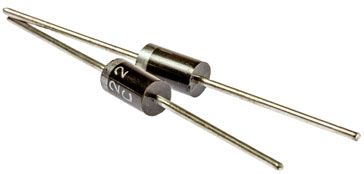
The diode also has a guard ring incorporated into the structure to make the diode more resilient to breakdown and along with this it also gives very low conduction losses and a low forward voltage drop.
The 1N5822 provides extremely fast switching and enables high frequency operation as a result of the Schottky structure.
In addition to this, the diode offers a high forward surge current capacity, and it also offers a higher reverse voltage than the 1N5820.
Video: 1N5822: An Amazing Schottky Diode You Must Discover
Key details and performance parameters for the 1N5822 diode.
| 1N5822 diode datasheet parameters & data |
|
|---|---|
| Parameters | Details |
| Diode type | 3A Schottky barrier plastic rectifier diode |
| Package type | DO201 |
| Repetitive peak reverse voltage, VRRM | 40V |
| Non-repetitive peak reverse voltage, VRSM | 48V |
| Working peak reverse voltage, VRWM | 30V |
| DC blocking voltage, VR | 40V |
| RMS reverse voltage, VR(RMS) | 28V |
| Forward continuous current, IF | 3A |
| Peak non-repetitive forward surge current, IFSM | 80A for 8.3ms |
| Power dissipation, PTOT | |
| Junction temperature (°C) | 125 |
| Forward voltage VF | 0.475V @ 3A |
| Reverse leakage IR | 2mA @ 20V @25°C |
Outline & pinout:

Explanation of major diode parameters
| Parameter | Explanation |
|---|---|
| Repetitive peak reverse voltage, VRRM | This is the maximum value of the short period peak reverse voltage that can be sustained. |
| Working peak reverse voltage, VRWM | This is the maximum value of the continuous reverse voltage that can be applied to the diode. |
| DC blocking voltage, VR | This is the maximum reverse DC voltage that should be applied across the diode. |
| RMS reverse voltage, VR(RMS) | As many AC waveforms are quoted in RMS, this is the maximum reverse voltage that can be sustained where the voltage is expressed in terms of its RMS value. |
| Forward continuous current, IF | This is the maximum forward current that can be sustained by the diode. |
| Average rectified current, IF | This is the maximum average current value that can be handled by the diode. The parameter often states the load as this will affect the operation of the diode. |
| Non-repetitive forward surge current, IFSM | This is the maximum surge current that can be handled - it should only be present for a short time. |
| Parameter | Explanation |
|---|---|
| Power dissipation, PTOT | The maximum power dissipation that can be sustained within the device. |
| Junction temperature (°C) | This is the maximum temperature of the PN junction that can be sustained. Remember that the junction temperature can be much higher than the ambient temperature of the equipment. |
| Forward voltage VF | This parameter gives the forward voltage drop for a particular current passed through the diode. |
| Breakdown voltage VBR | This is the minimum voltage at which the diode may breakdown. If the current is not limited it will lead to the destruction of the device. |
| Leakage current IR | This is the current that flows under stated conditions when the diode is reverse biassed. |
| Diode capacitance CD | The diode capacitance, CD may also be referred to as the junction capacitance, CJ. All diodes have a certain capacitance across the PN junction. The value will be stated for a given reverse voltage. |
| Reverse recovery time | If a diode is initially driven in forward bias, and the polarity suddenly switches to reverse bias, the diode will still remain conducting for some time. The reverse recovery time is the time required for conduction to settle into the reverse bias state. |
These are the main Schottky diode parameters that have been included in our list. There are others, but these help quantify the main elements of the performance of the diode.
Please note, that the data given is the best estimate we can give within a tabulated summary of this nature. Parameters also vary between manufacturers. Electronics Notes cannot accept any responsibility for errors, inaccuracies, etc, although we do endevaour to ensure the data is as accurate as possible.
Notes and supplementary information
• Availability & sources
The 1N5822 is available from a number of stockists and electronic component distributors many of which are given in the table below.
1N5822 Component Distributor, Stock and Pricing
• Further details
The 1N5822 is a relatively high current Schottky diode rectifier capable of a high forward surge current of 80A for 8ms.
This makes it ideal for many low voltage rectifier applications, although the low reverse voltage, a feature of silicon Schottky diodes can be an issue.
Being a silicon Schottky diode, it does not offer a huge reverse voltage capability, but the 1N5822 can withstand 40V as detailed within the data.
• Typical applications
Because of its combination of a 3 A continuous forward current rating, low forward voltage, and high switching speed, the 1N5822 is widely used across power electronics and DC-DC converter topologies.
Its primary application is serving as a freewheel (catch) diode in buck converters and boost converters operating at switching frequencies from tens of kilohertz up to hundreds of kilohertz.
It is also extensively used for reverse polarity protection in low-voltage battery-powered devices, output rectification in low-voltage switch-mode power supplies, solar panel bypass circuits, and inductive kickback suppression for relays and solenoids where switching losses must be kept to a minimum.
• 1N5822 development and backstory
The 1N5822 Schottky barrier diode was developed in the 1970s as part of the broader industry transition toward high-efficiency power conversion.
As switch-mode power supplies (SMPS) began replacing bulky linear power supplies in computing and industrial equipment, traditional silicon PN-junction rectifiers became a severe bottleneck due to their high forward voltage drop and slow reverse recovery times.
Semiconductor manufacturers including Motorola and General Instrument introduced the 1N5820 series (spanning the 1N5820, 1N5821, and 1N5822) to provide a high-current, low-voltage solution.
The 1N5822 quickly became the industry-standard 3 A, 40 V axial Schottky diode, establishing a benchmark footprint in the JEDEC DO-201AD package that remains widely produced today.
• 1N5822 key performance parameters
The performance of the 1N5822 is defined by several key electrical characteristics inherent to its metal-to-silicon Schottky barrier structure:
Low Forward Voltage Drop (VF): Typically dropping around 0.38 V to 0.47 V at lower currents and a maximum of 0.52 V at its full 3 A rated current, the 1N5822 incurs significantly lower conduction power losses compared to standard 3 A silicon PN junction rectifiers (such as the 1N5400 series, which typically drop ~1.0 V to 1.1 V).
Near-Zero Reverse Recovery Time (trr): As a majority-carrier device, the 1N5822 exhibits virtually no minority-carrier storage charge. This allows for extremely fast switching times, eliminating the transient reverse recovery current spikes and associated switching losses that plague standard PN junction diodes in high-frequency power supplies.
High Surge Current Capability: Despite its low voltage barrier, the 1N5822 is rated to handle non-repetitive peak surge currents (IFSM) of up to 80 A for a single half-sine wave pulse, offering robust protection against turn-on inrush conditions.
Reverse Leakage and Thermal Constraints: A critical design consideration is its reverse breakdown voltage (VR) rating of 40 V and a higher reverse leakage current compared to conventional silicon rectifiers—particularly at elevated temperatures. Thermal management is essential, as excessive junction temperature combined with reverse voltage can lead to thermal runaway if leakage losses are not properly dissipated.
In addition to these benefits the 1N5822 is widely available and cheap to buy making it deal for many low cost circuits.
 Written by Ian Poole .
Experienced electronics engineer and author.
Return to Component Data menu . . .