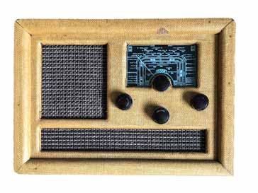
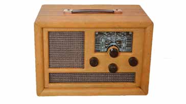
Double Decca BM5A, BM5B, BM5C Vintage Broadcast Radios
The Double Decca BM5 series radios were a transportable mains & DC battery powered 3 band 4 valve plus rectifier broadcast radio first introduced around 1940.
Radio Receiver History Includes:
Radio history / timeline
Radio receiver history
Superhet radio history
Classic vintage radio receivers
The Double Decca radios were a popular range of compact broadcast radios covering the long, medium and short wave bands.
The radios could be powered with by the internal mains power supply, or by a battery providing both the LT and HT supplies, although they would be very expensive to run from batteries.
Although the radios are designated as BM5A, BM5B and BM5C, there are also referred to occasionally, even in the Decca literature, as MB5A, MB5B, and MB5C.
Double Decca BM5A, B, C series basics
The Double Decca radio was aimed at the need for people having a home based radio, but also one that could be taken outside and powered from batteries. Although powering from batteries was very expensive, there were many radios of the time that could be powered in this way, some exclusively by batteries.
The original Double Decca MB5 was rather different to the models with the suffix letters, i.e. the MB5A, MB5B and MB5C. Although there are soem differences between the A, B, and C versions, these are relatively minor.
A summary specification for the radios is given in the table below.
| Double Decca BM5A, BM5B, BM5C Vintage Radio Performance Summary |
|
|---|---|
| Parameter | Details |
| Double Decca summary | Single conversion mains/battery powered superhet broadcast radio covering long, medium and short wave bands. |
| Launch date | Appears to be around 1940 |
| Frequency coverage: Long wave ; Medium wave ; Short wave |
|
| Power requirements | Line: 110*, 210, 230 and 250 Volts Batteries 1.5V & 90V |
| Intermediate frequency | 382 kHz |
| Aerial | Internal frame aerial for long and medium wave bands |
| Size | To be measured |
| Weight (no batteries) | To be measured |
* Although 110V was marked on the radio, the circuit diagram marked this tap as 100V
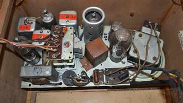
Valve line-up
The valve line-up included four valves or tubes for the radio receiver section, and a further valve to act as rectifier.
These valves were octal valves -†he type which was most common for the time when this radio was designed and initially produced.
| Valve / Tube Line-up for Double Decca MB5A, B, C Antique Radios |
||
|---|---|---|
| Valve Number | Type | Use within the circuit |
| V1 | 1A7EG | RF, frequency changer & local oscillator. |
| V2 | 1N5EG | Variable mu RF pentode acting as IF amplifier |
| V3 | 1H5G | Diode triode acting as AM detector and first audio amplifier |
| V4 | 3Q5GT | Pentode audio amplifier |
| V5 | 25Z6 | Power supply half wave rectifier |
Circuit description
The Decca BM5 or MB5 series of radios - note both BM5 and MB5 designations were used by Decca themselves, followed a fairly straightforward design line-up.
Warning: Like many radio sets of its day, this one does not have a transformer and as a result it is possible that the chassis or any attached metalwork could become live when the radio is attached to the mains supply. Great care must be exercised when working on these radios.
There was a heptode used as the RF / frequency changer and local oscillator, a single stage of IF amplification, and this was followed by a single diode triode to provide the AM detection as well as the AGC voltage and also the first stage of the AF amplification. There was a final pentode used to provide the audio output to the loudspeaker.
Each of the stages will be addressed in turn as the signal passes through the radio receiver.
• RF & frequency changer: V1
The signals are picked up by the frame aerial that is in the back panel of the set. There are two coils in this aerial, one for long and one for the medium waveband -- trimmer capacitors are also included to ensure the input RF tuning is correct. The required coil circuit is switched into circuit and tuned by a variable capacitor connected to the tuning dial.
The signal is applied to the grid of V1, a 1A7EG which operates as the frequency changer and there is also electron coupling for the local oscillator.
There is provision for the connection of an external aerial for the long and medium wavebands, and as no frame aerial loop is present for the short wave bands, although there is coupling to the loop aerial for short wave reception.
For an external aerial DC isolation is required to prevent the mains live voltage reaching the aerial or earth connection. To achieve this, a DC isolating capacitor is used in both the aerial and the earth connection lines.
Tuning for the local oscillator is provided using a set of internal coils and a variable capacitor ganged, i.e. mechanically linked to the capacitor used for the RF tuning. In this way the RF input tuning and the local oscillator track each other and provide the required rejection of image signals, etc.
• IF stage: V2
The second valve in the line up is a 1N5EG variable mu-RF pentode. This operates as the intermediate frequency amplifier stage running at a frequency of 382 kc/s.
The anode of the first valve has an RF transformer tuned to the IF and this is then coupled to the input of V2.
The selectivity of the set is provided by the two IF transformers in the anodes of V1 and V2. This provides adequate selectivity to enable signals on other wavelengths to be rejected and not cause undue interference.
AVC bias generated by the audio demodulator is applied to this stage and not the previous RF stage. This provides a reasonable AVC range to accommodate the varying signal strength level expected to be received. It acts to keep the output volume level the same for a variety of received input levels.
• Demodulation & 1st AF amplifier: V3
The signals from the IF stage are passed to detector and AF pre-amplifier. This stage consists of a single diode, triode valve 1H5G.
The diode detector takes in the IF signal which comprises a carrier which has the amplitude modulation superimposed on it. By rectifying the signal the audio component of the signal is extracted and the output is developed across a volume control which acts a load resistance.
This is passed via a coupling capacitor to the control grid of the triode amplifier and it is amplified.
The DC potential from the diode detector is also passed to a resistor capacitor network that serves to remove the modulation so that a DC voltage proportional to the signal level can be generated for the AVC.
• Final AF amplifier: V4
The final audio amplifier is based around a pentode, V4. This is connected to the previous audio amplifier via a coupling capacitor.
The output is connected to the loudspeaker through a matching transformer. A capacitor is placed across the input to the transformer to give a fixed level of tone correction.
• Power supply: V5
The radio had the option of either mains (power-line) operation with a wide input of between 110 and 250V with specific switch positions fort he differnet voltages as noted in the specifications table above. Also a DC input could be used and a number of radios of this era had a DC input capability. This was because there were still some households only supplied with DC around the time when this radio was launched.
The radio could also be operated from battery supply. An internal multi-gang switch was used to control which power source was to be used.
A combined LT and HT battery would have been purchased to run the radio for portable use, although the running costs must have been very high for this.

The mains supply took in the incoming power and dropped it as required using either dropper resistors or a resistive line cord.
Rectification of the AC power was provided by V5, a UY51. This only provided half wave rectification and so a Pi section smoothing filter consisting of an inductor and two capacitors was used.
The Double Decca BM5A, B, C series of radios were very good, and provided a good method of listening for many households. With the onset of WW2, these sets would have been a lifeline for many people as they kept up with the daily broadcast news and other radio programmes of the time.
 Written by Ian Poole .
Experienced electronics engineer and author.
More History:
Radio history timeline
History of the radio
Ham radio history
Coherer
Crystal radio
Magnetic detector
Spark transmitter
Morse telegraph
Valve / tube history
PN junction diode invention
Transistor
Integrated circuit
Quartz crystals
Classic radios
Mobile telecoms history
Vintage mobile phones
Return to History menu . . .