
R107 Radio Communications Receiver
The R107 is a vintage radio communications receiver dating from WW2 and used by the British Forces.
Radio Receiver History Includes:
Radio history / timeline
Radio receiver history
Superhet radio history
Classic vintage radio receivers
The R107 is a nine valve vintage radio communications receiver dating from WW2 - the design was completed around 1941.
The radio covered 1.2 to 17.5 Mc/s and was a nine valve (eight valves plus one rectifier) superhet or superheterodyne radio. Frequencies that were higher than around 18Mc/s tended not to be used for many military radio communications links of this nature at the time.
The radio had its own internal power supply for use on 100 to 250VAC as well as for being powered from a 12VDC battery supply as well. It also possessed its own internal loudspeaker although headphones were available and there was also a line output as well.
The radio was designed for receiving both CW (Morse) and RT (amplitude modulation telephony).
Although it could be used on its own as a communications radio receiver, it was also intended for use with transmitters, in particular, Wireless Sets No 12 and No 33 so that it could provide radio communications capabilities for fixed and some mobile situations.
The radio was deemed as a high performance radio receiver for use in large vehicles or fixed ground stations. However it was very robust because of the need for it to be relocated as the location of the radio communications base was changed.
These vintage radios came onto the surplus market in the 1960s and were widely available for a very reasonable cost. They were not as widely used as other radio communications receivers like the AR88, HRO, CR100 and the like, possibly because less were made and became available after the war.
However the weight is one of the main features of the radio as it weighed in at 96lbs, although it could be said the offered very good value in terms of cost / weight ratio.
R107 specification
The R107 vintage radio communications receiver had a level of performance that would be expected from a radio of this age.
At the time it was described as a high performance communications receiver, and it did have a reasonably good specification for a radio of this era and for use in a radio communications role.
The selectivity and sensitivity as well as the facilities on this vintage radio are all what would be expected from a radio dating from WW2.
The radio only used LC filters in the IF and therefore the selectivity was not as good as that of receivers which possessed soem from of crystal filter, but it was thought to be quite adequate for the situations in which it would be used, typically for use in establishing radio communications links.
| R107 Communications Receiver Performance Summary |
|
|---|---|
| Parameter | Details |
| R107 summary | Single conversion superheterodyne radio providing coverage within the MF and HF bands using eight valves for the receiver and one for the power supply rectifier. |
| Frequency bands |
Range 1: 17.5 - 7.0 Mc/s Range 2: 7.25 - 2.9 Mc/s Range 3: 3.0 - 1.2 Mc/s |
| Sensitivity | CW: about 1 µV for 20dB S/N AM: about 2 - 6 µV for 20dB S/N for AM carrier modulated to 30% at 400 c/s measured with selectivity switch in the narrow position. |
| Selectivity | There are two positions for selectivity: wide and Narrow Narrow: 3 kc/s at -6dB with an average cutoff slope of 15 dB per Kc/s offset Wide: 7.5 kc/s at -6dB with an average cutoff slope of 12dB per Kc/s offset. |
| Intermediate frequency | 465 kc/s |
| Audio filter | Passband: approx 300c/s centred around 900c/s |
| Power | 100 - 250V AC 12V DC Power consumption on AC is approx 31 watts |
| Weight | 96 lbs |
| Dimensions | 24 inches wide x 13 inches high x 17 inches deep. |
Comparatively few details about the performance were available in the manual with specifications like the image rejection and other parameters not quoted. Even the sensitivity specification is rather vague.
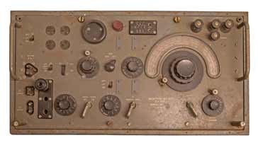
Receiver controls and receiver operation
The radio has a well spaced front panel which holds all the major controls and also includes a loudspeaker.
The operation of the R107 vintage radio communications receiver is quite straightforward and follows the normal pattern for radios of this type.
| R107 Communications Receiver Controls |
|
|---|---|
| Control | Details |
| Power switch | As expected this switch turns the set on and off. There is a separate internal switch to change between 100 - 250VAC and 12 DC. This is located towards the rear of the power chassis. |
| Sidetone switch | This switches the sidetone on and off - this is used in conjunction with a transmitter to hear the Morse signal being transmitted. |
| LS Switch | This turned the loudspeaker on and off. |
| Tel output control | |
| Audio filter switch | This switched the audio filter in and out. |
| Lim On / Off | This is referred to in the manual as a crash limiter. As the AGC was off for CW reception, it was necessary to limit and static crashes to reduce operator fatigue. It could also be used on AM, but with reduced efficiency provided the level controls were reduced. |
| BFO / AVC | This switched between the use of the BFO for CW reception and the AVC when AM / radio telephony was used. |
| IF Narrow / Wide | This switched the width of the IF section of the receiver. It changes the IF bandwidth between 3 kc/s for CW and 7.5 kc/s for AM reception. |
| Audio gain | This control was used to alter the audio output level. The manual suggests that it should be turned to 5 for initial operation. |
| RF gain | The RF gain was used to alter the gain of the earlier stages. Normally this would be left in a relatively high position or at maximum to gain the optimum noise figure and reduced to prevent overload on strong signals. |
| Main tuning | |
| Aerial trimmer | The aerial trimmer is used to provide the optimum signal by matching the antenna to the particular antenna used. |
| Range switch | |
Apart from the controls, the front panel also holds a number of connectors. The connections and controls are all available through the front panel as the receiver is contained in a steel case, and was likely to have been mounted to that only front panel access to the various controls and connections required would have been available.
| R107 Communications Receiver Front Panel Connections |
|
|---|---|
| Connection | Details |
| Muting & sidetone | This is a three pin socket that is connected to a transmitter to mute the receiver when the transmitter is in operation. |
| DC supply | The DC supply socket on the R107 communications receiver consists of a four pin connector. The upper and lower pairs are connected together in the receiver to provide the required current capacity. |
| AC Supply | This uses a two pin socket which is marked AC supply. |
| Panel jacks | There is a group of three socket holes towards the left of the receiver. The low pair are for headphones and are wired in parallel to allow two sets of phones to be used. The upper jack is for a 600Ω line. |
In use, the R107 communications radio receiver is relatively straightforward to use. The first stage is obviously to make all the relevant connections - power antenna, headphones if they are to be used, etc.
Before the radio is turned on, it is worth setting the AF gain to about mid position, and the RF gain possibly to mid position or to maximum if the AVC is switched in as this gives the best noise performance.
The radio can then be turned on. The range can be selected and the receiver can be tuned to the required frequency and the station can be finely tuned in.
The gain controls can be set for the prevailing signal and operating conditions. The filter can be set for narrow or wide - typically wide for amplitude modulation signals and narrow for CW or Morse.
The antenna trimmer can be adjusted to give the optimum signal as well.
R107 radio circuit summary.
In terms of its RF design, The R107 vintage communications radio is a nine valve single superheterodyne radio that has an intermediate frequency amplifier at 465 kc/s.
Of the valves eight are used in the receiver section and one is used as the power rectifier .
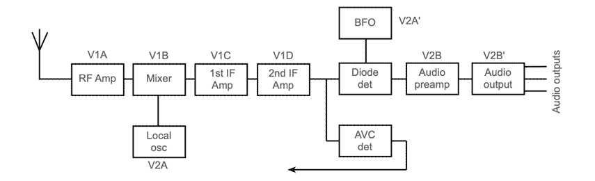
The valve line up in the RF design is as shown in the table below. The notation for the valves is a little unusual, but it is what was used in the manual, although this may not follow the standards used in circuit diagrams today.
| Valve Line-up for R107 Vintage Radio Receiver |
||
|---|---|---|
| Valve Number | Type | Use within the circuit |
| V1A | ARP34 (EF39) | RF amplifier |
| V1B | ARP34 (EF39) | Frequency changer (1st mixer) |
| V1C | ARP34 (EF39) | 1st IF amplifier |
| V1D | ARP34 (EF39) | 2nd IF amplifier |
| V2A | AR21 (EBC33) | Heterodyne oscillator (local oscillator for first conversion) |
| V2A' | AR21 (EBC33) | Beat frequency oscillator for CW |
| V2B | AR21 (EBC33) | 1st AF amplifier |
| V2B' | AR21 (EBC33) | 2nd AF amplifier |
| V3A | 6X5G | Power supply rectifier |
It will be seen that only two types of valve are used in the RF design apart from the power supply rectified. As the radio was operated in the field, spares were often needed, and having only two types of valve reduced the number of different types that were needed and this was a significant advantage.
One of the main features of the overall RF design of the R107 is that the circuit is constructed on three separate sub-chassis. These are the RF chassis, IF/AF chassis and the power chassis.
The radio has a sheet steel panel and framework and the three chassis are mounted onto this.
A detachable cover could be fitted over the controls to protect them when the radio was not in use. This could have been very necessary because it was quite possible that the radio might need to be moved very quickly if the location of the radio communications station needed to be changed, and it is quite likely that the radio would not be treated very gently, especially if the move needed to be undertaken very quickly.
In terms of its RF design, the R107 circuit blocks included the RF amplifier, frequency changer / mixer, two stages of IF amplification, an AM / CW demodulator and AF amplifier. There was also the local oscillator for the 1st mixer and a BFO for CW reception. A "crash" limiter was also included and was especially useful when the AVC was turned off.
The R107 communications radio receiver dates from WW2 and it was described as a high performance communications receiver. Although this vintage radio does not have the performance that would be expected today, for its time, the R107 performed well and was used in number of operational roles. It was very robust and contained within a steel case and the chassis and front panel were also steel. While this made the radio robust, it was also very heavy.
 Written by Ian Poole .
Experienced electronics engineer and author.
More History:
Radio history timeline
History of the radio
Ham radio history
Coherer
Crystal radio
Magnetic detector
Spark transmitter
Morse telegraph
Valve / tube history
PN junction diode invention
Transistor
Integrated circuit
Quartz crystals
Classic radios
Mobile telecoms history
Vintage mobile phones
Return to History menu . . .


