
RF / Microwave Circulator / Isolator Basics
RF or microwave circulators are typically three port devices based on ferromagnetic materials that steer RF power from one port to another, while isolating this power from the others and are therefore used in many mmWave, microwave and RF designs.
Home » Radio & RF technology » this page
RF Circulators Includes:
Circulator basics
RF or microwave circulators or isolators are devices that often used in microwave, mmWave and RF designs and they typically have three and sometimes four ports and they are used in RF system designs that require power from one port to be transferred to another whilst isolating power from the other.
RF circulators are used in many RF applications acting as a duplexer, allowing both transmit and receive functions to occur simultaneously, they are widely used in RF design applications including radar systems and a variety of professional radio communications systems.
RF circulators are receive their name because they transfer power from one port to the next, circulating it from say, entering at port one to output at port two, and entering at port two to exit at port three.
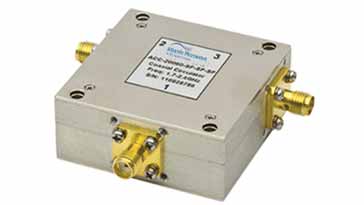
RF and Microwave circulators are available in a variety of forms for use in a variety of microwave and RF designs. Generally because they require relatively specialist materials and techniques they are available as commercially made items, but they come in a variety of formats and with a variety of forms of connector.
How an RF circulator works
The connections to RF circulators are normally called ports, and in addition to this they are normally numbered as 1, 2, 3, etc.
The RF circulator gains its name because it circulates the power entering one port only to the next one. A signal applied to port 1 will be passed to port 2: a signal input to port 2 will pass to port 3, but not back to port 1. An input to port 3 will pass to port 1, but not in reverse to port 2.

The ideal circulator will transfer all the power from one port to the required port, and none to any other. However in reality, there is always some attenuation in the transfer path, and some signal always leaks onto the ports that should be isolated.
The key RF circuit design challenge for these devices is to ensure the optimum transfer and isolation occurs.
Circulators may use strip-line printed circuit board technology (but normally using very low loss dielectric or PCB materials) and be contained within metal boxes with connectors or other connections to the outside world - some even use surface mount technology.
Other circulators may be based within waveguides and these can be used in RF system design applications that incorporate waveguide technology. The type of interface and technology that are need for any given instance will depend upon the RF circuit design for the application.In terms of their operation there most RF circulators are based around the use of ferromagnetic material. There are two main types:
Three port circulators: 3-port "Y-junction" circulators based on cancellation of waves propagating over two different paths near a magnetised material. Waveguide circulators may be of either type, while more compact devices based on strip-line are of the 3-port type.
Four port circulators: 4-port waveguide circulators based on Faraday rotation of waves propagating in a magnetised material. Using this technology, they are able to route the RF signals to four ports.
RF circulator circuit symbol
Like other electronic components, the RF circulator has its own circuit symbol that is used to represent it on electronic circuit diagrams or schematics for RF designs.
The basic symbol consists of the circle and an arrow showing the direction in which the power is circulated. Normally the ports are showin in order clockwise around the circle: Port 1, Port 2, and finally Port 3.

It is worth noting that each port, whether a coaxial feeder or waveguide, is shown as a single line rather than a pair of conductors.
3 port stripline technology circulators
One of the most commonly used forms of RF circulator is formed from a Y-shaped section of micro-strip or strip-line transmission line that is on a printed circuit board or other dielectric. The ports are placed 120° apart so that they are equi-spaced around a circle.

The printed circuit board assembly is then sandwiched between two laters of ferrite and then outside this, two strong magnets are fixed in place.
The assembly sets up a strong magnetic field axially through the ferrite discs and this focusses the magnetic field, called the bias, around the Y-junction.

When a signal is applied to one of the ports, an electromagnetic field is created in the strip-line, which interacts with the magnetic field from the magnets and there is a complex interaction between them. This results in the the signal only being able to travel to the next port around the circulator.
The circulator assembly consisting of the Y junction and the ferrite disks has a distinct resonant frequency - the assembly actually forms a resonator. For obvious reasons the circulator is not operated at this frequency, but either above or below it because the insertion loss, i.e. the attenuation is much lower.
RF circulator applications
There are several applications for RF circulators in a variety of RF circuit design applications. Normally they tend to be used at microwave frequencies and as a result they are often referred to as microwave circulators.
Duplexer: One of the most obvious and common applications for an RF circulator is within radar systems or radio communications systems where the transmitter and receiver use a common antenna.

RF circulator used as a duplexer Here the transmitter output is connected for example to Port 1, the antenna to Port 2 and the receiver to Port 3. Accordingly the transmitter power will circulate to the antenna, but not to the receiver, and the antenna received signals will circulate to the receiver.
In this way the receiver is isolated from the transmitter but the antenna has power from the transmitter and passes the received signal to the receiver without any mechanical switching.
RF Isolator: The RF circulator can be used as an RF isolator. These are useful for protecting a transmitter output amplifier has to run with a high level of VSWR.
As high voltages or current levels can be experienced by the power amplifier if connected directly to the antenna under these circumstances it is possible for the amplifier to be damaged by them. Often transmitters need to operate over a wide bandwidth and under these circumstances, a good impedance match is unlikely to be maintained over the whole bandwidth and damaging levels of VSWR could be seen.
To overcome this issue a circulator can be used to protect the PA from the effects of the reflected power by isolating it from te reflected power which is directed to a different port and dissipated there.
For this the transmitter is connected to Port 1 and the antenna to Port 2. Port 3 is typically connected to a 50Ω load - this is required because the levels of isolation are dependent upon having a good impedance match presented at the different ports. If a poor match or open circuit is presented, then the isolation performance will be impaired.

RF circulator used as an isolator The transmitted power is passed from Port 1 to Port 2 and travels to the antenna. Any reflected power will return along the feeder and pass from Port 2 into Port 3 where it can be dissipated in the load. In this way, the RF power amplifier will be able to operate with a high feeder VSWR, but being protected by the circulator acting as an RF isolator.
The load on Port 3 is required to provide a matched impedance: isolators need matched impedances onth e ports to maintain the level of isolation from that port.
RF circulator & isolator specifications
Understanding the different specifications for an RF circulator enable the correct decisions to be made for a specific RF circuit design or system. Explanations for some of the key specifications appropriate to RF circulators are given below:
Frequency: RF circulators have a limited frequency range over which they operate satisfactorily. The frequency range is limited by the isolation provided between the ports and directions that should not be coupled and the insertion loss that can be achieved.
Typically, RF circulators can operate between frequencies of about 750MHz up to 20 GHz or so, although specialised (and expensive) designs can be made to work on bands between 100 MHz and 100 GHz.
Each RF circulator will be able to operate over a small band. One example on the market now can operate over 3 - 6 GHz, another 7.9 GHz to 8.4 GHz, and so forth. There are naturally many other examples, often designed for specific RF circuit design applications for satellites, radar, etc . .
Impedance: Like all feeders and other electronic components that are included in RF power transfer, a characteristic impedance needs to be specified. The most popular impedance level for RF circulators is 50Ω.
Insertion loss: This is the attenuation measured in dB of the incident signal from one port to the next, i.e. in the forward direction. Typical figures might be in the range from 0.1 to 0.75 dB. The figure will depend upon the actual circulator, its frequency band and other factors.
Generally, the insertion loss of a circulator / isolator loss increases with frequency. Selecting a circulator with the lowest loss will be particularly important where high powers are involved to preserve the transmitted power - at higher powers, there will be more loss in the circulator, and one that can handle the required power is essential as a result.
Isolation: This figure is the attenuation in the reverse flow direction measured n dB. It is typically between about 17 and 35 dB. If greater levels of isolation are needed, then it is possible to place two RF circulators in series.
Power handling: The power handling specification for RF circulators is particularly important where high power levels are used. As the wiring and ferromagnetic materials will only be able to handle certain power levels it is important these are not exceeded otherwise performance could be sacrificed, or the component could be irreparably damaged. Power levels are typically measured in dBm, dBw or Watts.
Package type: Circulators are available in a wide variety of packages. Typically they come in manufacturer standard packages with connectors, although other formats including: Drop-In, Surface mount technology, etc are available.
Connectors: For those RF circulators that are connectorised, the type of connector is important. Two of the most popular types of connector are SMA and N-type. SMA is ideal for lower power levels and where space is at a premium, and N-type for higher power levels. It should be remembered that SMA connectors themselves can handle surprisingly high power levels.
VSWR: The VSWR or voltage standing wave ratio indicates how good the match is to the required impedance level. VSWR levels of between 1:1.2 and 1:1.5 are typically achieved.
Although there are more specifications that will be seen in the data sheets for these electronic components, the ones detailed above are the more important ones that will be needed to select the particular device for a given RF design.
RF circulators and isolators are widely used in many microwave and other RF circuit design applications. Everything from radio communications equipment to radar, and many other applications. The fact that they transfer power from one port to another specific port only enables them to be used as duplexers allowing a transmitter and receiver to operate at the same time on nearby frequencies, as well as enabling RF power amplifiers to operate into loads that present a poor impedance match.
In view of their specialised nature, RF circulators tend to be bought in as an electronic component, and as a result there are several different electronic component distributors that are able to supply a range of these products for almost every RF design.
 Written by Ian Poole .
Experienced electronics engineer and author.
More Essential Radio Topics:
Radio Signals
Modulation types & techniques
Amplitude modulation
Frequency modulation
OFDM
RF mixing
Phase locked loops
Frequency synthesizers
Passive intermodulation
RF attenuators
RF filters
RF circulator
Radio receiver types
Superhet radio
Receiver selectivity
Receiver sensitivity
Receiver strong signal handling
Receiver dynamic range
Return to Radio topics menu . . .


