
Superhet Radio AGC - Automatic Gain Control
The automatic gain control, AGC within a superhet radio enables the gain of the receiver to be controlled to level the audio output, but to prevent overloading.
Home » Radio & RF technology » this page
Superhet Radio Circuit Blocks:
Block diagram / overall receiver
RF amplifier & tuning
RF mixer
IF amplifier & filter
Automatic gain control, AGC
Superhet Radio Includes:
Superhet radio
Superhet theory
Image response
Block diagram / overall receiver
Design evolution
Double & multi-conversion superhet
Specifications
The automatic gain control, AGC, was introduced to stop variations in signals causing large variations in the received volume. Accordingly the AGC was also often called an automatic volume control or AVC.
Large variations in signal caused by fading on the medium wave broadcast bands or on the short wave bands can lead to large changes in volume at the output of a radio if no action is taken. Also when using a radio in a vehicle on AM, large variations in signal strength can occur.
To combat these types of issue, the automatic gain control or automatic volume control was introduced - the term automatic volume control, AVC being used considerably less widely these days.
Whilst the automatic gain control still serves to control the output volume, a well designed AGC system will also help ensure that the receiver does not become overloaded in the presence of strong signals.
AGC requirements
An automatic gain control needs to be implemented so that it enhances the reception. Unfortunately this is not always easy to achieve and sometimes a poorly implemented AGC can detract from the reception under some circumstances.
Two of the main requirements of an AGC system in a superheterodyne receiver are that it should ensure that the audio or other output does not vary over such a wide range that the audio output continually needs adjusting. With many superhet radios being used to receive amplitude signals like AM or SSB, some control over the final output is needed otherwise the audio output will vary widely. As signal can vary over a range of more than 70 or 80 dB, the audio needs to be controlled accordingly.
The other requirement is that it is possible that when receiving strong signals, some stages of the receiver become overloaded. This can lead to issues like desensitisation, cross modulation and even the reception of spurious signals generated in the receiver if the RF or mixer stages overload. Also if any stages of the receiver became overloaded then any amplitude information could become distorted.
AGC implementations
The implementation of an automatic gain control will depend on the design of the radio and its overall capabilities.
Typically the control voltage for the AGC is derived from the last stages of the receiver. There are several options that can be used:
- Demodulator output: the most widely used sources of the AGC voltage are from the demodulator. For AM it is necessary to ensure that the carrier level is detected and not the modulation level. The audio regenerated for the audio stages is not suitable as it has often been passed through a capacitor to remove the DC level. Also the time constants for any filtering will not be correct.. Accordingly another output from the diode detector is taken retaining the DC and the filtered to give the required AGC time constants.
- Audio stages: Sometimes an output may be taken from the audio stages. This may be useful for signal modes like single sideband and Morse, CW. This removes the issue of the beat frequency oscillator required for these modes adding being present and affecting the AGC level.
- IF stages: On some occasions a separate output may be taken from the IF amplifier and passed into a separate demodulator using separate circuitry.
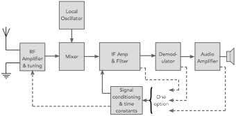
This AGC voltage is then applied to the IF and often the RF stages. Normally the AGC is applied to the RF stages in higher performance radios as some lower end broadcast receivers may not have RF stages that can accommodate an AGC.
The AGC is normally applied so that it reduces the gain of the IF stages first, and then as the incoming signal increases in strength, the AGC voltage is also applied to reduce the gain of the RF stages as well. In this way the signal to noise performance of the superhet receiver is maintained when it is needed.
AGC characteristics
The AGC in any superhet radio will have time constants associated with it. If not time constants were applied, then the AGC would be fast and remove any amplitude information from the incoming signal.
The AGC needs to be able to enable the signals to be received to fall within an acceptable range, and it also needs to accommodate the effects of fading for whatever reason. Two time constants can be used:
- Attack time: This is the time taken for the AGC system to respond to a sharp change in signal strength.
- Decay time: This is the time that it takes for the AGC to return to its value after a signal is removed, or a transient like noise disappears.
Also the time constant are different for different types of modulation:
- Amplitude modulation: Even though AM is not widely used these days, except for broadcast transmissions, most communications receivers are able to accommodate it. The automatic gain control voltage detects the carrier level and uses this as the control signal. Often this voltage is generated within the envelope detector, and it is filtered to remove the amplitude modulation, whilst still being able to see the signal strength variations. Typical time constants may be between 0.1 and 0.3 seconds. Often a slightly faster “attack” time is used to accommodate any large noise bursts.
- Morse: Morse / CW signals have a very different characteristic to that of amplitude modulation. The effective data rate is much lower, and therefore longer time constants may be needed so that the AGC is not continually changing with the signalling. If this happens the constant change in background noise level can be very distracting, if not annoying. Also the fact that a beat frequency oscillator is required can mean that this signal can be seen by the AGC detector. This can be overcome by using the detected audio level to generate the AGC voltage, although this can lead to issues when the audio frequency falls below the audio bandwidth or rises above it, but still within IF bandwidth. Typical attack times for Morse can be 20 ms and decay can be 200 to 500 ms or so to allow for the gaps between the Morse elements.
- Single sideband: The situation for SSB is very similar to that of Morse. As the signal has no carrier, the signal is constantly varying in strength according to the variations in speech. Again a beat frequency oscillator is required, and as a result many receivers use the recovered audio to generate the control voltage for the automatic gain control for the superhet receiver. Tin terms of the time constants a relatively fast attack time is used and a longer decay time. Often up to a second as this accommodates pauses in speech whilst also being able to follow any variations due to fading, etc. If the AGC decay time was too short this would give rise to a swift increase in background noise during speech pauses.
- Frequency modulation: For frequency modulation, any amplitude variations can be disregarded as the modulation is only carried as frequency variations. Accordingly the latter stages of the IF are normally driven into limiting to remove any amplitude variations. By only allowing the latter stages of the IF to limit, spurious signals are not an issue. Only if the RF or mixer stages limit are unwanted spurious signals generated. The AGC may still be used to prevent overload in the RF stages, but this needs to be generated from a circuit prior to the limiting in the IF.
In some receivers the AGC time constants are switched by the mode switch on the set. In other receivers it is possible to have a separate control where the time constants can be set according to the requirements. It may also be possible to turn the AGC off as well.
The design of a very good AGC system needs to suitable reduce the gain f the IF and also the RF stages to preserve the signal to noise ratio and also ensure that the output signal from the superhet receiver is maintained at a suitable level.
 Written by Ian Poole .
Experienced electronics engineer and author.
More Essential Radio Topics:
Radio Signals
Modulation types & techniques
Amplitude modulation
Frequency modulation
OFDM
RF mixing
Phase locked loops
Frequency synthesizers
Passive intermodulation
RF attenuators
RF filters
RF circulator
Radio receiver types
Superhet radio
Receiver selectivity
Receiver sensitivity
Receiver strong signal handling
Receiver dynamic range
Return to Radio topics menu . . .


