RF In-Line Power Meter: inline wattmeter
In line wattmeters or power meters are able to measure the RF power being transferred from a source to a load by sensing the power flowing in the feeder.
RF & microwave power meter Includes:
RF power meter
PEP, average, & pulse power
Power measurement techniques
In-line power meter
Absorption-power meters & sensors
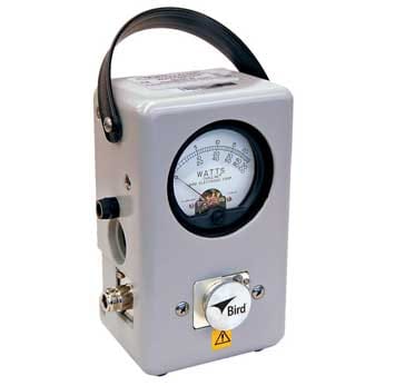
RF inline power meters or wattmeters are connected into a feedline and can measure the power flowing from the source to the load, and also in the reverse direction.
The inline wattmeters or power meters use a directional coupler to couple a small amount of power from the feedline into the sensor itself.
The big advantage of an RF inline wattmeter is that they can measure power whilst it is being delivered to the load, i.e. they can be used for testing an operational system. Absorptive power meters form the load and the power cannot be delivered to another load.
One of the iconic RF inline wattmeters is the Bird 43 Thruline ® wattmeter which has been in use for many years and is still widely used today.
Inline wattmeter concept
The inline RF wattmeter is based around the use of a directional coupler. This is an RF circuit element that couples a small amount of the power flowing along a feeder into the secondary circuit which is used for measuring the power in the feeder. The amount of power is small in the secondary circuit is small and does not introduce any undue loss.
Using this technique it is possible to separately detect power flowing in either direction, i.e. forward power and reverse power which has been reflected from the load due to mismatch, etc. In this way an inline wattmeter can be sued for measuring the VSWR, voltage standing wave ratio in a feeder.

The circuit is a very simple form of directional coupler and illustrates the basic concept. Accurate inline power meters use more components to enable more accurate results to be obtained over a wider frequency band.
In the circuit the transmitter and load are connected by a feeder, and this is coupled to two additional short lines within the RF inline power meter. On each of these coupled lines there is a resistor used for impedance matching, and a diode - the position of these relative to the direction of power flow determines whether forward or reflected power is measured.
The diode acts to rectify the coupled power so that it can be directly read by a meter and the capacitor removes the residual RF.
In many inline RF wattmeters, only a single coupled line is used, and the components switched to select the forward and reverse power measurement.
The advantage of the inline power meter capability means that the power meter can be kept in circuit whilst the load is active. This can be particularly useful if the load needs to remain active whilst the power is measured - this cannot be achieved using an absorption wattmeter.
 Written by Ian Poole .
Experienced electronics engineer and author.
More Test Topics:
Data network analyzer
Digital Multimeter
Frequency counter
Oscilloscope
Signal generators
Spectrum analyzer
LCR meter
Dip meter, GDO
Logic analyzer
RF power meter
RF signal generator
Logic probe
PAT testing & testers
Time domain reflectometer
Vector network analyzer
PXI
GPIB
Boundary scan / JTAG
Data acquisition
Return to Test menu . . .