How to calibrate a Vector Network Analyzer, VNA
Before using an RF vector network analyzer, VNA, it is necessary to calibrate the system so that cable lengths and other uncertainties are removed.
RF vector network analyzer includes:
What is a VNA
VNA calibration
VNA specifications
Scalar analyzer
Calibration is a key issue for any test equipment to ensure that the readings made fall within the set limits.
For an RF vector network analyzer, calibration is particularly important. Not only does the test instrument itself need to undergo a formal period calibration to ensure that the unit itself is operating within the manufacturers limits, but it also needs a user calibration.
This user or systematic calibration is needed to ensure that the effects of cables, connectors, etc are nulled out before the measurements of the device under test are made using the vector network analyzer, VNA.

Periodic equipment calibration
Like any other item of electronic test equipment, an RF network analyzer requires the equipment to be calibrated. In this way it can be assured that it will give results within the parameters set out in its data sheet.
As all test instruments vary over time, it is necessary to calibrate them against standards that can be traced back to the internationally agreed standards.
Specialised calibration laboratories are able to undertake this, and for any electronics test and development laboratory, it is a key requirement that all test equipment is calibrated periodically - normally the equipment manufacturer will advise on the recommended calibration periods.
Systematic user calibration
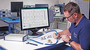
One of the key activities that must be undertaken before using a vector network analyzer, VNA is to calibrate the system as a whole.
Cables, connectors, the test fixture and the like all systematic errors into the system and they must be nulled out before the VNA network analyzer is used so that correct measurements can be made.
Errors in the system include:
- Reflection loss As a result of slight mismatches there will be some loss as a result of the reflections.
- Phase differences introduced by the leads All leads will have an electrical length, and this can be accommodated by performing the user calibration.
- Transmission loss The cables or other means of transferring power from he VNA network analyzer to the device under test will introduce some loss. As frequencies can be very high, this loss can be noticeable, and even if small it can alter the results.
- Directivity at Port 1 Errors as a result of the directivity at port 1.
- Source matching at Port 1 The fact that the source cannot provide a perfect match to the feeder can introduce a measurement uncertainty and even if small it needs to be accounted for.
- Load matching at Port 2 However good a load is made to be, there will never be a totally perfect match.
- Crosstalk Some of the signal will bypass the device under test and transfer from its input to the output without passing through the device. However much the system is screened some signal will bypass the device under test.
By calibrating the VNA network analyser system before use these errors can be virtually removed and normally this is very easy to achieve. Often a user may perform a user calibration of the system before each measurement is made as phases may change, cable routing may change and this can all cause differences which need to be nulled out.
When using very high frequencies, even moving the cables can cause changes - even if high quality phase stable cables are used, small differences can be seen that might change the results of the tests with the RF network analyzer.
Some different techniques may need to be adopted according to the test system and the application - understanding the different techniques available enables the fastest and most accurate calibration to be achieved.

Note torque wrench for connectors
The first step in the process of user calibration of an RF network analyzer is to perform some simple visual checks and actions:
- Check connectors: It is essential that the connectors used with the vector network analyzer are not damaged in any way. With repeated use, by even the most careful of users it is possible that wear and damage can occur. It is necessary to inspect for dirt in the connectors and also any signs of wear or damage. If anything is suspect, then it should be replaced.
- Clean connectors: Even if no dirt is seen, then it is still worth cleaning the RF connector to remove any hidden dirt. At high frequencies, even small amounts of dirt can cause major issues. Compressed air is the best way of achieving this. It should be less than about 50psi otherwise it may cause damage itself. Isopropyl alcohol may also be used in addition to remove any grease, but do not apply with a cloth as this may leave small fibres.
- Connect the connectors to the system: When connecting the connectors to the VNA system be careful to only screw the outer section of the connector that is intended for a screw action. Let the centre be drawn in. Although it is sometimes tempting to turn the whole connector, never do this as it can cause undue wear and damage to the precision inner.
- Tighten with torque wrench: When tightening the connectors, always use a torque wrench as this will ensure that the correct tightness is achieved without over tightening which can result in damage to the connectors. Be careful not to cause damage to the connectors on the vector network analyzer itself as these will be very costly to replace.

VNA user calibration techniques
There are several techniques that can be used for the user calibration of a VNA network analyzer system.
The VNA user calibration technique chosen will depend upon a variety of factors including the system used, the accuracy needed vs time taken, etc.
- SOLT: The acronym SOLT standards for: Short, Open, Load, Through. It is one of the the most straightforward ways of calibrating an RF vector network analyzer. To undertake this form of VNA network analyzer user calibration known standards with a short circuit, open circuit, a precision load (usually 50 ohms) and a through connection are needed.
This form of user calibration is less suitable for waveguide measurements as it is difficult to obtain an open circuit or a load. - TRL: This abbreviation stands for Through Reflect Line and it is a form of VNA user calibration that can be used with non-coaxial systems like fixtures, wafer probing, or with waveguides.
The TRL technique uses a line with a corresponding characteristic impedance as its reference impedance, replacing the match, and is ideally an air line. It is possible to manufacture an air line with characteristic impedance more precise than that of a fixed match, so the technique delivers higher effective directivity, improving the test port match. - TOM This technique employs fully-characterized standards and together the two, one-port standards open and match produce four equations that are supplemented by four additional equations for the through standard. Connection of incorrect or defective standards as well as faulty electrical connections can be detected immediately after this calibration technique is complete.
In addition to these there are also several other methods of calibration that can be used.

Calibration standards for RF network analyzers
In order to provide the short circuits, open circuits, and matched loads, etc. These vector network analyzer calibration standards, which are typically one-port and two port network are manufactured to a very high standard. These have virtually ideal properties, although they will naturally deviate by a small amount from the ideal as they are real items.
In view of the standard to which they have been manufactured, they are not cheap items to buy and they are normally kept safely often in a protective wooden box. This helps ensure that ensures they do not sit unprotected on a bench where they can be damaged very easily. These cal standards should be looked after as they can easily be damaged if left on a bench.
In view of the fact that it is impossible to manufacture perfect calibration standards, this is overcome by providing the VNA with the deviations of the standards in terms of a data file. This enables the RF network analyzer to considerably reduce the errors that would occur even with the calibration standards. In this way it ensures that the vector network analyzer can provide the greatest possible accuracy for its test results.
There are several elements to a VNA calibration kit:
- Short circuit: A coaxial short circuit can be constructed with almost ideal characteristics, enabling total reflection of the incident energy. Within the short circuit there will be a small length offset as a result of the distance between the reference plane and the physical short. Fortunately the signal loss that occurs over this short length can be ignored, and the offset introduced by the physical length can be entered into the system. In some instances the parasitic inductance of the short length can be accounted for by including it in the data passed to the vector network analyzer.
Vector network analyzer calibration kit short circuit - Open circuit:
A coaxial open circuit standard has to use an enclosed approach to provide screening and avoid the pick-up of stray electromagnetic energy. At the open end of the inner conductor, a frequency-dependent fringing capacitance is formed. Even if an open standard could physically be constructed with zero length, the fringing capacitance would still result. This creates a negative imaginary part for S11 at higher frequencies as a result of the capacitive reactance.
Vector network analyzer calibration kit open circuit - Matched load: The matched load in the VNA calibration kit provides a precision broadband impedance. The impedance will be the same as the characteristic impedance for the system - virtually always 50Ω. There are several methods of achieving this, but one approach is to have the inner conductor terminating into a resistively coated substrate. The actual resistance can then be trimmed by creating holes in the substrate using a laser.
- Through line: The other main type of attachment using in a vector network analyzer calibration kit is a through connection. This is a two-port standard and it allows direct connection of two test ports. This type of attachment is designed to give a minimum loss and also a relatively short length. The loss and length are normally accommodated within the characteristics provided to the analyzer itself. They can be accurately determined and provided manually if needed. The through line is assumed to be a very close match to the characteristic impedance used.
User calibration is an integral part of using an RF network analyzer. By ensuring that the system is properly calibrated the uncertainties arising from the connections to the device under test can be removed. Without the user calibration of the vector network analyzer, the lengths of the leads and characteristics of the device holder, etc, all come into the system, and the actual characteristics of the device under test are lost.
 Written by Ian Poole .
Experienced electronics engineer and author.
More Test Topics:
Data network analyzer
Digital Multimeter
Frequency counter
Oscilloscope
Signal generators
Spectrum analyzer
LCR meter
Dip meter, GDO
Logic analyzer
RF power meter
RF signal generator
Logic probe
PAT testing & testers
Time domain reflectometer
Vector network analyzer
PXI
GPIB
Boundary scan / JTAG
Data acquisition
Return to Test menu . . .


