What is a Voltage Divider or Potential Divider
A potential divider or voltage divider is a circuit that takes a larger voltage and divides it down by a fixed ratio according to the electronic components to give a smaller output voltage.
Voltage Includes:
What is voltage
Electric field
Voltage / potential-divider
Electromotive force
A voltage divider or potential divider is one of the most basic circuits used in electronic circuit design, and one that is widely used because it provides a very important function.
As such the voltage divider is a fundamental element of any electronics circuit design, and also many electrical designs as well.
The circuit for the voltage divider or potential divider is very simple. It just consists of two electronic components which are typically resistors.
Video: What is a Potential Divider
What is a potential divider
The potential divider is normally created using just two electronic components which are typically resistors.
The circuit essentially consists of two resistors in series, normally connected between the input voltage and zero volts / ground. The junction between the two resistors then has a small proportion of the input voltage appearing across it.
The potential divider is a very useful method of reducing the voltage within a circuit with a minimum of electronic components.

The diagram shows two basic formats for laying out the circuit schematic for a voltage divider. Both circuits are exactly the same from an electrical viewpoint, but they may be seen in either format in various circuit diagrams.
It can be seen that the full input voltage labelled Vin appears across both of the resistors in series. As the same current passes through both resistors, assuming there is no load on the output, the output voltage will be a proportion of the input voltage.
The output voltage can be calculated from the formula given below.
Manipulating the equation, it can be seen that the ratio of the output over the input voltage is equal to the ratio of R It is relatively easy to manipulate the formula so that if you need a particular output voltage from a fixed input voltage, the values of the resistors can be calculated quite easily. For example if the input voltage is 9 volts, and a 6 volt output is needed, the first decision to make is the overall resistance level that is needed. This is a decision that is normally made as a result of other electronic circuit design constraints. For this example, let's make it easy and say that the overall resistance is 9kΩ. Using the formula, we can see that R R1 is 3kΩ and R One of the issues with the potential divider is that if the output has a resistance placed across it then it will alter the operation. In reality any circuit connected to the output of the potential divider will act as a load and will alter the operation slightly. However in many cases the effect is small and it can be ignored. Where the resistance is more comparable with the resistance values in the potential divider or voltage divider, then its effect must be accommodated. This is easy to achieve by looking at the circuit. The new overall resistance of the bottom resistor in the voltage divider is R2 in parallel with R3. If we call this resistor Rt, then this is easy to calculate from the fact that it is two resistors in parallel. It is easy to calculate the new value for Rt using the formula for two resistors in parallel. Having calculated this value, it can then be placed into the formula for the voltage divider: In this way it is easy to calculate the effect of any loading by the circuit following the voltage divider. However, the electronic circuit design of the circuits is often chosen so that the voltage divider resistances are much lower, often ten times is a good factor, and in this way the effect of any loading is minimised. There are very many electronic circuit designs that use a simple voltage divider within them. The examples are too many to include all of them, but a couple of examples are given below: Volume control in a radio
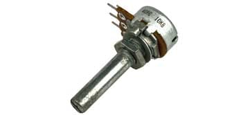
A potential divider using a variable resistor system is the most common way of incorporating a volume control into a radio or other analogue audio system. Instead of varying the resistance of a resistor, a fixed resistance element is used, and the output point from the resistor is changed as seen in the circuit symbol. It can be imagined from the circuit symbol, that there is a contact that slides along the resistor element. In this way when the slider is close to the top of the resistive element, a much higher voltage will be seen, but when it moves down the voltage seen will be reduced. In this way the volume of the audio signal can be changed very easily. The electronic components that operate in this way are known as potentiometer, gaining this from the potential divider description. A typical applications for the potentiometer is within a domestic radio where it enables the volume to be adjusted to the required level. The volume control is normally placed just after the signal has been demodulated and at the input to the audio amplifier. It can be seen that the incoming audio from the demodulator is connected to the top of the potentiometer, and the slider is set to tap off the required proportion of the incoming voltage. It is set to give the required potential division for the audio level that is needed. Potentiometers come in a variety of formats. The one shown above is circular, but linear ones are also used and often seen as the sliders in audio mixer consoles etc. Setting DC bias level in a transistor circuit designWhat happens of the output drives a low resistance

Examples of voltage divider in real circuits


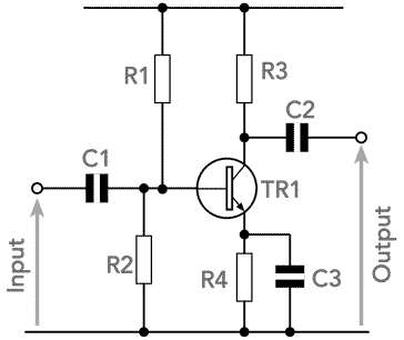
The straightforward circuit for the common emitter transistor circuit shown above uses a potential divider comprised of the two resistors R1 and R2 to set the bias for the transistor.
By selecting the right values the voltage on the base can be set to the value needed for the circuit in question.
If the resistors in the voltage divider chain are set low enough, but not too low so that they draw too much current, the base will not load the circuit unduly, and the voltage will be maintained at the right level.
The voltage divider, or potential divider circuit both terms are used - is a particularly useful circuit configuration that is used in very many areas of electronic circuit design. It uses very few electronic components and enables a lower voltage to be created from a larger one very easily and simply.
In view of this the potential divider is seen in a host of areas of electronic circuit design, and often used as second nature to divide a voltage or signal to provide one of the required level.
 Written by Ian Poole .
Experienced electronics engineer and author.
More Basic Electronics Concepts & Tutorials:
Voltage
Current
Power
Resistance
Capacitance
Inductance
Transformers
Decibel, dB
Kirchoff's Laws
Q, quality factor
RF noise
Waveforms
Return to Basic Electronics Concepts menu . . .