Home » Component data » Transistor data » this page
OC44 Transistor Data
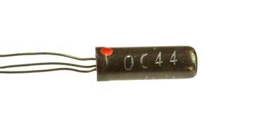
Key transistor data for the OC44 PNP RF germanium transistor including key electrical parameters, pinout, package type and many other key transistor datasheet details.
The OC44 was a PNP germanium transistor used for RF applications with an fT of 8 MHz. It was aimed at low RF frequencies and was used in a variety of transistor radios in the RF sections of the circuit.
The transistor was very popular in the late 1950s and early 1960s as it was able to work as an RF device, although its fT was only 8MHz, but this was high for the time.
Key datasheet details and performance parameters for the OC44 transistor.
| OC44 transistor datasheet parameters & data |
|
|---|---|
| Parameters | Details |
| Transistor type | PNP germanium RF transistor |
| Package type | X02 |
| VCBO max (V) | -15 |
| VCEO max (V) | -15 |
| VEBOmax (V) | -12 |
| IC max (mA) | 10 |
| TJ Max °C | 80 |
| PTOT mW | 83 |
| fT min (MHz) | 8 |
| COB | 12 |
| hfe | 100 min |
| IC for hfe | 1 mA |
| Similar / equivalents | |
Outline:
![]()
Pinout:
![]()
Explanation of transistor parameters
| Parameter | Explanation |
|---|---|
| VCBO Max | Maximum collector-base voltage with emitter open circuit . |
| VCEO Max | Maximum collector-emitter voltage with base open circuit. |
| VEBO Max | Maximum emitter-base voltage with collector open circuit. |
| VCEsat (included where applicable) | The voltage drop across the collector-emitter when the transistor is fully saturated (acting as a closed switch). |
| IC Max | Maximum collector current. |
| Parameter | Explanation |
|---|---|
| TJ | Maximum junction temperature. |
| PTOT Max | Maximum device dissipation normally in free air at 25°C unless other conditions indicated. |
| fT Min | Minimum cutoff frequency at which the current gain in a common emitter circuit falls to unity. |
| COB Max | Maximum collector capacitane, normally measured with emitter open circuit. |
| hFE | DC current gain for HFE at IC. [Note hfe is the small signal gain and although this may be slightly different, the transistor current gain will vary considerably from ne transistor to the next of the same type.] |
| PTOT Max | Maximum device dissipation normally in free air at 25°C unless other conditions indicated. |
These are the main transistor parameters that have been included in our list. There are others, but these help quantify the main elements of the performance of the transistor.
Please note, that the data given is the best estimate we can give within a tabulated summary of this nature. Parameters also vary between manufacturers. Electronics Notes cannot accept any responsibility for errors, inaccuracies, etc, although we do endevaour to ensure the data is as accurate as possible.
• Notable features
The OC44 is a vintage PNP germanium bipolar junction transistor developed by Mullard (Philips) in the late 1950s, renowned for its low-noise performance and role in early RF and audio circuits, including the iconic Dallas Rangemaster treble booster.
Germanium Construction: Provides warm, vintage tone with low noise and high linearity, ideal for audio fidelity in pre-1960s electronics.
High DC Current Gain: Minimum hFE of 100 at IC=1 mA, enabling efficient amplification with minimal base drive.
RF-Capable Frequency Response: Cutoff frequency (fT) minimum of 8 MHz, supporting low-frequency RF applications. While this is very low for modern devices, this was a very high cutoff frequency for devices of the 1950s and early 1960s.
Low Collector Capacitance: Maximum Cob of 12 pF, minimizing signal distortion in high-impedance circuits.
Compact X02 Package: X02-style encapsulation for reliability enabled many vintage circuits using it to remain operational for many years.
Low Power Rating : Maximum dissipation of ~80 mW, suited for small-signal, battery-powered devices.
Vintage Reliability: Alloy-junction design and glass encapsulation made it resistant to early semiconductor reliability issues - still sought for retro builds and vintage radio maintenance.
• Typical applications summary
| Application Category | Typical Use Case | Device Feature Utilised |
|---|---|---|
| RF Amplification | RF/mixer stages in superheterodyne transistor radios. | 8 MHz fT and low Cob (12 pF) for low-frequency RF signal integrity. |
| RF radio circuits | Applications in many super-regenerative radios which were popular at the time. | High fT of 8 MHz enabled this device to be used in these areas. |
| Audio Pre-Amplification | Low-level signal boosting in phono stages and tone controls. | High hFE (100 min) and low noise for clean, distortion-free audio. |
| Guitar Effects Pedals | Treble booster circuits like the Dallas/Arbiter Rangemaster. | Germanium warmth and high gain for classic rock tone shaping. The higher fT enabled the top end frequencies to be handled better than on some other transistors. |
| General Audio Circuits | Preamp and driver stages in vintage amplifiers. | |
| Switching Applications | Low-power logic and relay drivers in early electronics. | 10 mA Ic max - the high fT for its time enabled 'fast' switching to be achieved - the fast is applicable to the time! |
 Written by Ian Poole .
Experienced electronics engineer and author.
Return to Component Data menu . . .