Bush DAC90A Vintage Broadcast Radio
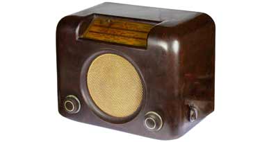
The Bush DAC90A is an iconic British vintage radio which was introduced in 1950 and is well sought after in the collectors markets today.
Bush Radios Includes:
Bush DAC90A
Bush TR82 transistor portable
Iconic radio receivers:
Summary of iconic radio receivers
Radio receiver history
Crystal radio sets
Development of the superhet radio
Radio history / timeline
The Bush DAC90A is the successor to the DAC90. It used more modern valves and an updated circuit when compared to its popular predecessor.
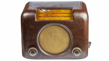
The DAC90A is easily recognised by its unique styling and bakelite case.
Covering the medium and long wavebands it was targeted at the lower end of the market, making it an accessible and popular radio for all.
Video: Bush DAC90A
Bush DAC90A background
The DAC90A radio was produced by the Bush Radio company which was formed to produce radios in 1936.
After the Second World War, Bush produced the DAC90. This radio as launched in 1946 and became a success. It was aimed at the lower end of the market, making it a good radio for the mass market.
As a result of developments with valve technology and the success of the DAC90, the DAC90A was developed.
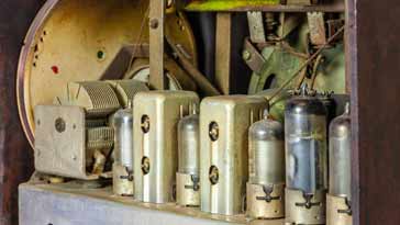
Launched in February 1950, the DAC90A used the new B8A series Rimlock valves which had a small "nub" on the side of the glass envelope to engage with a slot in the socket to ensure the correct orientation.

Apart from the valves themselves, further improvements were made to the circuit to improve the overall performance and reliability.
When the DAC90A was introduced in 1950, it cost £12 1s 8d for the walnut or brown version, and £12 16s 9d for the cream version. These prices had purchase tax which was an additional UK tax added to these prices.
Although black and white versions are talked about in some areas, it does not appear that any versions of these colours were made. Some may have been painted these colours, but they were not part of the main production output. In any case white bakelite cannot be made as it turns out a cream colour as a result of the material used.
The DAC90A was very successful and continued production until around 1959 when transistorised radios started to become available.

DAC90A specifications
The performance of the DAC90A was quite reasonable considering its date of manufacture and the fact that it was a lower cost radio intended to appeal to as many people as possible.
| Brief Specification for the Bush TR82 Broadcast Radio |
|
|---|---|
| Parameter | Specification |
| Basic description | A transportable broadcast superheterodyne radio covering intended for domestic use on the long and medium wave bands. |
| Coverage | Long wave 1070 - 1900 metres Medium wave 187 - 560 metres ** |
Intermediate frequency | 465kHz |
| Power requirements | AC or DC mains of 200 - 250V 40 - 100 c/s |
| Valve complement | 4 valves for the radio section plus one for the power rectification |
| Case details | Cream or brown bakelite cabinet |
| Dimensions | 12.7 x 9.1 x 7.9 inch / 305 x 236 x 192 mm (w x h x d) depth does not include the power connector. |
| Weight | 4.5kg / 9 lb |
** note that the coverage is not given as a frequency in Hz, but as the wavelength in metres. This was common at the time for domestic radios.
DAC90A circuit description
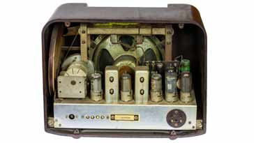
The DAC90A was a five valve superhet radio where four valves were used for the radio receiver itself and one valve was used as the input supply half wave rectifier.
Warning: the set does not have a transformer and as a result it is possible that the chassis or any attached metalwork could become live when the radio is attached to the mains supply. Great care must be exercised when working on these radios.

| Bush DAC90A Valve Line-Up |
||
|---|---|---|
| Valve Ident | Valve Type | Circuit Function |
| V1 | UCH42- triode hexode | RF, mixer & local oscillator |
| V2 | UF41 - pentode | IF amplifier |
| V3 | UBC41 - double diode triode | Audio & AGC detectors, audio 1st amp |
| V4 | UL41 - output pentode | Audio output |
| V5 | UY41 - half wave rectifier | Power rectification |
There are several elements to the overall DAC90A circuit description.
• RF elements: The signal is picked up by an internal frame aerial or antenna. This is located to the right hand side of the cabinet when looking from the front. The frame antenna is effectively an inductor and this is tuned by a two section variable capacitor with the other section being used for the local oscillator. There are also two section of the frame coil and only part is used for the medium wave, the remainder being shorted out. In this way it becomes resonant on both bands using the same variable capacitor.
• 1st mixer and local oscillator: V1 is a triode hexode UCH41 is used as the basis for the first mixer and local oscillator.
The signal from the frame antenna is applied to the control grid of the hexode section of the valve that acts as an RF amplifier and mixer.
The triode section of V1 is used as the local oscillator which has a tuned transformer with one winding connected from grid to ground and the other winding in the anode. This provides the feedback required for oscillation.
The signal resulting from the mixer is passed to the next stage through an IF transformer placed in the anode circuit of the hexode section of V1.

• IF stage: The signal from the mixer is passed to a single stage IF amplifier. This is formed around V2 which is a UF 41 pentode. Additional selectivity is provided by the second IF transformer which is located in the anode circuit of the amplifier.
• Detector and first audio amplifier: Once amplified by the IF amplifier, the signal passed to V3, a double diode triode UBC41. This acts as a detector for the RF signal and it also provides an AGC voltage to apply to the grids of V1 and V2. This reduces the effect of signal variations on the output audio.
The triode section of this valve also provides the first stage of audio amplification, bring the level up from the relatively low levels after detection / demodulation.
• Audio output: The amplified audio is passed to V4, a UL41 output pentode. This brings the level of the audio up to a sufficient level to drive the internal loudspeaker.
• Power supply: The radio accepts both AC and DC because at this time, not all households had access to AC mains supplies. The use of DC gave another option for powering the set.
The incoming power was rectified by a half wave rectifier and smoothed using a Pi section consisting of two capacitors and a resistor.
Where lower voltages were required in the circuit a large dropper resistor was used to reduce the voltage, but this gave off considerable heat and the resistor was accordingly quite large.
Points to note
The DAC90A is a well respected radio and most of these vintage radios perform very well. However it is worth remembering that they can be over 70 years old now, and at this sort of age these radios can start to fail.
The radios have some old wax capacitors in them, and now these will always need changing as they will already be working poorly and could completely fail. When renovating one of these radios, it is always worth replacing these capacitors.
Often the main smoothing capacitor may be OK, but it is worth taking a careful look at it. Look for signs of bulges in the end cap as this can be a sure sign of an impending disaster. It is also worth looking at the leakage current to see whether this is acceptable. The smoothing capacitors are a dual electrolytic type, and although they may appear to be a specialised component, they are still available at specialist suppliers.
One of the main points to note is that the audio coupling capacitor can fail. If this happens it can destroy the output valve, the UL41 and it could also take the output transformer with it. When restoring a DAC90A, this capacitor should be replaced as a priority.
The Bush DAC90A is a very popular vintage radio. It is often used in movies where depictions of the 1950s UK are required. Its brown (or cream) case, the round speaker and the slanted dial panel as well as the overall styling are very reminiscent of the period.
The radio itself was simple and straightforward, built to a cost and accordingly with a minimum number of components and stages.
The radio was very popular at the time and now many DAC90A radios can be found at collectors fairs and on the Internet.
 Written by Ian Poole .
Experienced electronics engineer and author.
More History:
Radio history timeline
History of the radio
Ham radio history
Coherer
Crystal radio
Magnetic detector
Spark transmitter
Morse telegraph
Valve / tube history
PN junction diode invention
Transistor
Integrated circuit
Quartz crystals
Classic radios
Mobile telecoms history
Vintage mobile phones
Return to History menu . . .


