
GECoPHONE BC2830 Vintage Radio
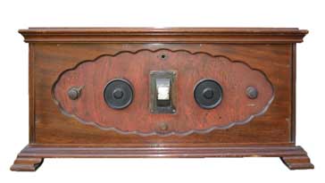
The GECoPHONE BC2830 was a magnificent example of a TRF vintage radio of the 1920s using three valves / tubes and housed in a wooden cabinet of mahogany.
GEC and GECoPHONE Radios Includes:
GECoPHONE No 1 (BC1001 & BC1002)
GECoPHONE BC2830 TRF
GEC BC3960 superhet
Iconic radio receivers:
Summary of iconic radio receivers
Radio receiver history
Crystal radio sets
Development of the superhet radio
Radio history / timeline
The GECoPHONE BC2380 is one of the long line of vintage radios produced in the Gecophone line that graced many well off family's living rooms in the 1920s and 1930s.
The General Electric Company in the UK produced a number of radios in the 1920s and 1930s under the brand name of GECoPHONE.
The first radios were crystal sets, but with the advancements in technology they used the new valve / tube technology to produce a series of tuned radio frequency, TRF sets and then superheterodyne radios.
GECoPHONE BC2830 basics
The GECoPHONE BC2830 is a TRF, tuned radio frequency vintage radio receiver using three valves / tubes and requiring external or battery power for both the high tension (high voltage) supply (two supplies) as well as for the heaters. An internal grid bias battery was also needed.
| GECoPHONE BC2830 Vintage Radio Performance Summary |
|
|---|---|
| Parameter | Details |
| BC2830 summary | The valve TRF radio |
| Date of introduction | Circa 1927 |
| Cost at introduction | £19 12s 6d |
| Wave range (frequency coverage) | 230 - 3100 metres |
| Number of valves | 3 |
| Principle of operation | Tuned radio frequency with reaction / regeneration |
| Output capability | Headphones or loudspeaker |
| Power | Batteries or external power. The BC2830 requires a single LT supply and two HT supplies marked “Det” and “LF”. An internal grid bias battery was also needed. |
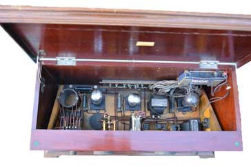
The aesthetic design for this vintage radio was impressive as it used mahogany wood for the case which looks really good. It was intended for table top placement and used a fine wooden case with a lid that opened to reveal the electronics. This opening lid was very useful as the batteries would require replacing periodically.
BC2830 circuit line-up
The GECoPHONE BC2830 followed a fairly standard format for the time, using three valves and a TRF format.
Video: What's Inside a 1920s Vintage Radio: GECoPHONE BC2830
Little did the purchasers of the time know, but within only a very few years, technology would move on and far more convenient to use radios using the mains electrical supply would be available. Not only this, but they would also use the superheterodyne format which provided much greater levels of performance.
However, for its time, the radio performed reasonably well. It utilised a three valve format consisting of a regenerative detector circuit which increased the Q of the tuned circuit giving additional gain as well as detecting the signal.
All the valves used were triodes as valves using additional electrodes were not commonly used at the time of the design.
The radio used the valves available at the time and the line up is as summarised below.
| Valve / Tube Line-up for GECoPHONE BC2830 Antique Radio |
||
|---|---|---|
| Valve Number | Type | Use within the circuit |
| V1 | 210HL | Triode valve. Other equivalents may also be found in the radio: CV1050 CV2571 HL2K K30C K30D K30K PM2HL VT50. |
| V2 | PM1LF | Audio triode. Other equivalents may also be found in the radio: 210LF; VR27; VT50; CV1027; CV1050; HL2K. |
| V3 | PM202 | Output triode. Other equivalents may also be found in the radio: CV1246; CV1023; NT82; P2 but not the earlier bright emitter P2. |
All valves used 2 volt heaters, and these were all suitable for battery power.
In addition to the external HT supplies and the LT for the heaters a grid bias battery was located internally. This was a 9 Volt pack with taps every 1 .5 V. This provided different voltages for the three valve grids and may have required periodic adjustment for example after valve replacement. Grid bias batteries lasted for years as virtually no current was drawn. They were not even disconnected by the on-off switch.
The LT would have been powered by a 2V lead acid accumulator that would need to be taken to the local wireless shop for charging. The two HT supplies would have been zinc carbon dry batteries of the correct voltage. A variety of different voltages were available for different radios, but they were costly and this meant that at this time when AC power was not used for these radios, the running costs were high and accordingly valve radios were only used by those who could afford it.
There were four main front panel controls:
| Main Panel Controls |
|
|---|---|
| Control | Details |
| Range | This was the band change switch to select long or medium wave. |
| Intensifier | This controlled the feedback in the leaky grid detector. Increasing the control gave greater feedback which increased the gain and selectivity. If the control was advanced too far, then it would first be on the point of oscillation and create distortion and then it would oscillate giving unpleasant beat notes. The reaction control used a variable capacitor in conjunction with the fixed circuit inductance rather than what was termed a "swinging coil" approach where the proximity of inductors controlled the feedback level. |
| Selector | This was the tuning control |
| Volume control | This varied the output level using the stepped potentiometer. |
A further unmarked switch is present. It was located in the centre at the bottom, underneath the tuning dial. It was a two position pull / push switch with only four wires going to it.
Another interesting aspect of these radios is the capacitors used. IN these radios there are some that could be mistaken for wire wound resistors, of which there are also some.
The 'wire-wound capacitors' were very interesting but quite unusual. They were made by taking a metal rod and covering it with a thin layer of insulation and then winding a coil of tinned copper wire.
The turns were soldered together along one side to make them non-inductive. One connection was made to the metal rod and the other to the winding layer. These capacitors were used extensively in many early GECoPHONE wireless sets including the GECoPHONE crystal sets.
Type approval and BBC stamp
In the very early days of 'wireless' broadcasting in the UK, a group of manufacturers decided that in order for broadcasting to be a success, a national broadcasting system needed to be set up and funded. Without this, there would be no reason for people to buy broadcast radios.
Part of the funding came from a receiving licence, and part as a levy or royalty on each radio that was sold. Each radio also needed to be type approved by the General Post Office in the UK.
The system was inaugurated in 1922, and each radio bore what was called the BBC stamp. Although the scheme was discontinued in 1924, many radios still bore a BBC mark. It tended to give a level of confidence to prospective purchasers and it acted as a good sales point.
The BC2830 bore one of these marks on its top lid as shown int he photograph.
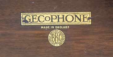
This must have been one of the last radios to bear the BBC stamp as manufacture started around 1927 when the scheme for using BBC stamps was ended.
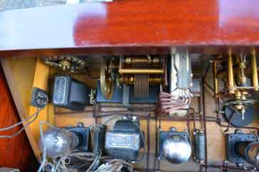
The GECoPHONE BC2830 is not one of the most widely available vintage radios these days. However it is a fine example of the engineering used in these early radios or wireless sets. The very neat wiring and general construction are really quite remarkable.
 Written by Ian Poole .
Experienced electronics engineer and author.
More History:
Radio history timeline
History of the radio
Ham radio history
Coherer
Crystal radio
Magnetic detector
Spark transmitter
Morse telegraph
Valve / tube history
PN junction diode invention
Transistor
Integrated circuit
Quartz crystals
Classic radios
Mobile telecoms history
Vintage mobile phones
Return to History menu . . .


