
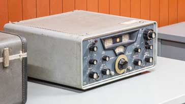
Hallicrafters SR-2000 Hurricane Transceiver
The Hallicrafters SR 2000 transceiver is a vintage HF amateur radio rig covering 80, 40, 20, 15 & 10 metre bands and giving 2KW PEP output on SSB.
Hallicrafters Radios Includes:
SR 2000 (Hurricane)
Iconic radio receivers:
Summary of iconic radio receivers
Radio receiver history
Crystal radio sets
Development of the superhet radio
Radio history / timeline
The Hallicrafters SR 2000 was a ham radio transceiver capable of delivering 2KW PEP input on the HF ham radio bands of the time. The model number indicates its power rating.
This vintage radio transceiver was launched in 1965 and was manufactured until about 1972 when imports from Japan started to erode the market for western manufactured equipment.
With this transceiver the Hallicrafters SR 2000 provided a very neat solution for anyone wanting to deliver a full kilowatt output to the antenna with no external linear amplifier.
The SR 2000 is also referred to as the "Hurricane". This name was part of the Hallicrafters marketing as they had a number of amateur radio equipments at the time named after storms: tornado, cyclone, etc.
To this day, there is a good following for Hallicrafters equipment and they appear on the vintage radio sales and in the second hand markets where they still command a good price but represent good value for money.
Although they do not have all the bells and whistles and computer control, etc of modern equipment, they can still perform well on todays amateur radio bands.
Hallicrafters company
The Hallicrafters company was founded in 1932 by William J Halligan and was based in Chicago, Illinois, USA.
The company produced a variety of radio equipment, but it is probably best known for its radio communications equipment, including a large variety of amateur radio or ham radio equipment including radio receivers, transmitters and transceivers.
One of their first pieces of radio equipment as the SX-9 Super Skyrider radio communications receiver launched in 1935.
However they produced a wide variety of other equipment, suspending normal operations during WW2 to produce military equipment.
After the war, the company returned to manufacturing radio equipment, the company employed over 2500 people at one stage. At this time they were manufacturing equipment for missiles and electronic warfare equipment. Hallicrafters also produced a wide variety of similar other high value equipment.
However the development production of amateur radio equipment continued, and they produced a number of high performance and classic vintage radios, transceivers and the like for general purpose use and specifically for amateur radio.
Finally the company was sold to Northrop-Grumman in 1966, and although the factory was kept, the name was sold on.
SR 2000 basic specification
The Hallicrafters SR 2000 offered a very good level of performance for its day and the specification reflected this.
| Hallicrafters SR 2000 Main Specifications |
|
|---|---|
| Parameter | Details |
| Summary | Ham band double conversion superheterodyne transceiver for the HF amateur radio bands providing a full 2kW input power level (1kW output). |
| Frequency coverage | Full frequency coverage of the amateur radio bands of the time in eight 500 kc/s ranges: 80 metres: 3.5 to 4.0 Mc/s 40 metres: 7.0 to 7.5 Mc/s 20 metres: 14.0 to 14.5 Mc/s 15 metres: 21.0 - 21.5 Mc/s 10 metres: 28.0 - 28.5 Mc/s 10 metres: 28.5 - 29.0 Mc/s 10 metres: 29.0 - 29.5 Mc/s 10 metres: 29.5 - 30.0 Mc/s |
| Power | SSB high power: 2kW input, 1kW output SSB low power: 1kW input, 500W output CW: 900 W input, 500W output |
| Calibration accuracy | 2kc/s error after indexing at high frequency end of band |
| Frequency stability | Less than 250 c/s drift in first hour and after 15 minute warm-up and better than 100c/s thereafter. |
| Tube complement | 19 tubes plus one voltage regulator and 22 diodes |
| Receiver sensitivity | 1µV or less for 20dB signal to noise ratio (emission type not defined). |
| Intermediate frequencies | 6 - 6.5Mc/s first IF, and 1650kc/s second IF. |
| Selectivity | 2.1kc/s at -3dB and 4.2 kc/s at -50dB using 1650 kc/s six pole filter |
| Power supply requirements | Power is supplied by matching power supply P-2000 [this also includes a loudspeaker]. |
| Dimensions | 7 ¾ x 16 ½ x 15 inches |
| Net weight | 26 lbs |
The radio was introduced in 1965 and many people comment on its superb performance, especially for the date it was introduced. The cost at launch was $1095.00 which meant that it was not a cheap rig, although a linear was not needed to bring the power up. That said, it was very approximately in the same price bracket as the Collins KWM2 which cost $1150 in 1959 when it was launched, but its power output was much less as it had two 6146 tubes in the output.
This vintage radio also needed a power supply. There was a matching power supply which included a loudspeaker and meters for the key measurements, but this as a further $450.
Another accessory that was available was an external VFO, HA-20. This provided the capability to operate on separate frequencies, further apart that the incremental tuning would provide. This capability was available on many later vintage radio transceivers for ham radio, and this was capability on the SR 2000 Hurricane was well ahead of its time.
Hallicrafters SR 2000 valve line-up.
The SR 2000 had a total of 19 tubes which provided the different functions within the overall HF radio communications transceiver.
| Tube Line-up for Hallicrafters SR 2000 Vintage Radio Communications Transceiver for Amateur Radio |
||
|---|---|---|
| Tube Number | Type | Use within the circuit |
| V1 | 12DK6 | Receiver RF amplifier |
| V2 | 7059 | Receiver and transmitter first mixer |
| V3 | 7059 | IF amplifier and AALC amplifier |
| V4 | 12AT7 | 2nd receiver mixer and VFO amplifier |
| V5 | 7059 | Noise amplifier and pulse amplifier |
| V6 | 6GX6 | 1st 1650kc/s amplifier and blanker |
| V7 | 7059 | 2nd 1650kc/s amplifier and side tone amplifier |
| V8 | 7059 | AGC amplifier and meter amplifier |
| V9 | 12AT7 | Product detector and 1st audio amplifier |
| V10 | OA2 | Voltage regulator |
| V11 | 7059 | 2nd transmitter mixer and 100 kc/s crystal oscillator |
| V12 | 7056 | Heterodyne oscillator |
| V13 | 12BA6 | VFO |
| V14 | 12AT7 | BFO / Carrier oscillator and 3rd microphone amplifier |
| V15 | 6AQ5 | Audio output |
| V16 | 8122 | Transmitter power amplifier |
| V17 | 8122 | Transmitter power amplifier |
| V18 | 12BY7A | Transmitter PA drive |
| V19 | 12AT7 | 1st and 2nd microphone amplifier |
| V20 | 12AT7 | VOX amplifier and relay amplifier |
Note: It is worth noting soem unusual tube types. the 7056 (V12) is a 7 pin miniature sharp cut-off pentode, the 7059 (V2, 3, 5, 7, 8, 11) is a 9 min miniature medium mu sharp cut-off pentode, and the 8122 (V16 & 17) is a very small, low-cost, forced-air- cooled beam power tube designed for use as an RF power amplifier.
SR 2000 circuit summary
The SR 2000 Hurricane transceiver follows a fairly traditional approach when compared to other transceivers, especially later ones. However it incorporates a number of very nice capabilities which sets it out above many other similar vintage radio communications transceivers.
The transceiver consists of a double conversion superheterodyne receiver with a matching double conversion topology for the transmitter which shares a lot of the circuitry to enable full transceive operation.
Accordingly the heterodyne crystal oscillator, variable local frequency oscillator and the carrier frequency oscillator all contribute to the transmit and receive functions.
In addition to this both IF stages are used for both transmit and receive along with the six pole lattice crystal filter which provides adjacent channel selectivity in receive and unwanted sideband as well as some carrier suppression on the transmit side.
Receiver circuit operation
The signals enter the receiver from the antenna via the transmit receive switch and then enter the RF tuning and RF amplifier stage based around V1 which is a 12DK6 pentode tube.
The output from this stage is then passed to first mixer which is a 7059 medium mu sharp cut-off pentode. The first oscillator is crystal controlled and therefore the first IF spans a band of frequencies - 500 kc/s from 6.0 to 6.5 Mc/s.
In the first IF bandpass tuning is applied to ensure that unwanted signals do not enter the further stages of the radio. Amplification is also provided by V3 which is another 7059 pentode.
The signal then progresses to the second mixer using V4 where it is mixed with the variable frequency local oscillator based around V13. This converts the signal down to the second IF stage which has a fixed frequency of 1650 kc/s. This is higher than the 465 kc/s IFs used in many radios, but it provides improved image rejection and hence a reduction in the level of spurious signals that might be received.
The VFO stage incorporated adjustment for the VFO frequency. To enable shifting between receive and transmit as well as upper and lower sideband, a varicap or varactor diode was incorporated into the circuit. This enabled the required VFO frequency to be obtained as required.
The first stage of the second IF is based around V6, and with the noise blanker set to the "OFF" position, the stage amplifies in the normal way. When the blanker control is adjusted for maximum noise rejection, then the noise amplifier stage based around V5 amplifies the noise from the first IF. The signal and noise pulses are then detected and shaped into positive going pulses by the semiconductor diode CR7. The detected signal predominantly consists of noise and it is amplified by the pulse amplifier stage, V5B. The negative going pulses are then fed to grid 3 of the IF amplifier and blanker stage of V6. These pulses interrupt the amplifier stage for the duration of the noise spike, removing the crashes that might otherwise be heard.
This is a far more sophisticated and effective form of noise blanker than the back to back diodes used in so many other radios.
The signal is then passed through the crystal lattice filter to provide the adjacent channel selectivity. For its day, this gave exceptional levels of selectivity and ease of use.
The second IF had two stages of IF amplification, and then the signal was split. One feed went to the product detector - the transceiver only operated on SSB and CW and therefore no AM detector was needed. The other feed went to the AGC detector. The AGC voltage was used to control the gain of the RF amplifier and first IF, thereby limiting the effect of overload on the rest of the receiver.
Once the signal was demodulated, the signal was passed to the audio amplifier where it was amplified to speaker level or for use with headphones.
SR 2000 transmitter section
In many respects the transmitter section of this vintage radio follows the reverse of the receiver, although with a high power final amplifier.
The transmitter signal starts where audio enters the rig from the microphone. It is amplified in three stages using V19a, V19b, and V14b. The signal is then used to modulate the carrier which is around 1650 kc/s, but this is done with a two diode balanced modulator which suppresses the carrier to produce a double sideband suppressed carrier signal.
This signal is then passed though the crystal lattice filter to give a single sideband suppressed carrier signal and then it is amplified by one stage of what is the receiver IF.
The signal is then passed to the transmitter first mixer stage where it is mixed or heterodyned with the VFO to give a signal in the 6.0 - 6.5 Mc/s range.
The signal passes though the bandpass filters of this area of the radio and on tot he second transmitter mixer, V11a. This signal is then mixed with the crystal oscillator signal to bring it tot he final output frequency.
Here the signal is amplified by the transmitter driver amplifier, V18 and then passed to the final amplifier consisting of V16 and V17 - two 8122s that can provide the full legal power limit in the USA.
The output from this stage is passed into a Pi network to enable the output to be properly matched to the feeder impedance at the required frequency. The signal is also passed through the transmit receive switching to route the signals as required.
Introduced in 1965, the Hallicrafters SR 2000 Hurricane transceiver is a vintage radio that provided excellent performance for its day. It gave the full legal US power output without the need for an external linear amplifier and on top of this the circuit had some very nice refinements not found on many other transceivers. Even today, years after Hallicrafters closed, there is a following for the equipment and rightly so because t represented soem of the finest in ham radio engineering of the day.
 Written by Ian Poole .
Experienced electronics engineer and author.
More History:
Radio history timeline
History of the radio
Ham radio history
Coherer
Crystal radio
Magnetic detector
Spark transmitter
Morse telegraph
Valve / tube history
PN junction diode invention
Transistor
Integrated circuit
Quartz crystals
Classic radios
Mobile telecoms history
Vintage mobile phones
Return to History menu . . .


