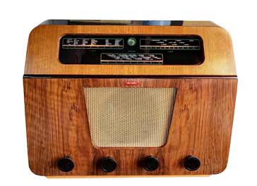
Murphy A170 Vintage Radio Receiver
The Murphy A170 is a vintage radio that was introduced in 1950 as a quality broadcast radio capable of covering the long, medium and short wave bands.
Murphy Vintage Radio Equipment Includes:
Murphy A170
Iconic radio receivers:
Summary of iconic radio receivers
Radio receiver history
Crystal radio sets
Development of the superhet radio
Radio history / timeline
The Murphy A170 is a not a radio that is widely seen in the second hand and vintage radio collectors markets, but nevertheless it is a radio of interest.
The Murphy A170 was aimed at the mid to higher end of the market as it offered a better quality of reproduction than some other radios of its day, and it also contained a number of capabilities and functions that were not normally found in other radios of its day.
Murphy Radio Company
Murphy radio was a British manufacturer of radios that was formed in 1929 by Frank Murphy and E J Power..
At this time many people were still using crystal radio sets, although many had progressed to tuned radio frequency radios.
By the time the 1920s had turned into the 1930s, the superhet radio was starting to appear on the British market.
The company later manufactured television sets and with Bush in 1962. However the name Murphy, still lives in in the form of some radios made in the Far East.
Murphy A170 performance specification
The Murphy A170 vintage radio is known for the good performance it provided. With its large loudspeaker and various other refinements, it was able to provide a good level of preformance, especially when compared to many other radios of its day.
The basic radio was designated the A170, but there was also a gramophone version referred to as the A170R. This had the same radio, speaker, etc, but it was housed in a much larger cabinet to provide space for the additional capability.
The A170 radio was manufactured at the Murphy manufacturing plant in Welwyn and their plant in Dublin, and the A170R gramophone was only manufactured in Dublin.
| Murphy A170 Receiver Performance Summary |
|
|---|---|
| Parameter | Details |
| Murphy A170 summary | Single conversion superheteroheterodyne broadcast radio providing coverage within the MF and HF bands using four valves within the radio, one as a tuning indicator (magic eye) and a final valve as the power supply full wave rectifier. |
| Frequency bands |
Short: 16 - 52 metres Medium: 190 - 560 metres Long: 1000 - 2050 metres |
| Intermediate frequency | 465 kc/s |
| Loudspeaker impedance | 3 Ω |
| Extension loudspeaker | 3 - 7 Ω |
| Power requirements | A170: 200 - 250 VAC 50 - 100 c/s A170R: 200 - 250 VAC 50 c/s |
| Fuse | Temperature fuse on mains input |
| Scale lamps | Two 6.3 V 0.3A MES style lamps |
| Power consumption | A170: 52 W A170R Radio: 52 W A170 gramophone: 81W |
| Cabinet dimensions | A170: 17 in high x 22 in wide x 8 in deep A170R: 36 in high x 22 in wide x 17 in deep |
| Weight | A170: 25 lb A170R: 72 lb |
| Release date | Welwyn manufactured A170: April 1950 Dublin manufactured A170: September 1950 Dublin manufactured A170R: October 1950 |
| Cost at launch | United Kingdom A170: £23 14s 7d plus purchase tax Dublin A170: £34 15s 0d for A170 Dublin A170R: £61 |
A170 circuit
The radio followed a similar format to most other vintage radios that were used for broadcast reception.
The radio was a single conversion superhet, and although this followed the standard topology, it hd a number of nice features and the overall engineering and circuit design was such that it provided above average audio quality.
This vintage radio had a total of six valves which included the power supply rectifier and a "Magic Eye" tuning indicator.
| Murphy A170 Valve Line-Up |
||
|---|---|---|
| Valve Ident | Valve Type | Circuit Function |
| V1 | 6C9 - triode hexode | RF amplifier, 1st oscillator & mixer |
| V2 | 6F15 - RF pentode | 1st IF amplifier |
| V3 | 6M1 Magic eye | Tuning indicator |
| V4 | 6LD20 - double diode triode | Detector and 1st audio amplifier |
| V5 | 6P25 - output beam tetrode | Audio output |
| V6 | UU9 - double diode rectifier | Power supply rectifier |
In terms of the circuit, the radio followed a fairly standard format for a broadcast superheterodyne radio of its era.
The radio had a single valve to provide the RF, mixer and local oscillator functions, a single IF amplifier, a diode detector, and amplifier.

The radio was designed to operate with an external long-wire antenna. Accordingly connections for the aerial and earth were provided at the back of the radio.
The signals entered the radio and apart from the standard RF tuning an additional rejector circuit was used on the input to remove any signals that might be picked up by the antenna on the same frequency as the intermediate frequency amplifier.
For the radios manufactured at the Welwyn site, a low impedance coupling winding was used on the medium wave section with a parallel; resonant rejector circuit placed in series with the antenna. For radios manufactured in Dublin a series resonant "acceptor" circuit was used across the main input. Either circuit worked equally well.
Once through the IF removal circuits, the main RF tuning was present which was tuned and then presented to the grid of the frequency changer or mixer circuit. This was based around the hexode section of V1, a 6C9.
The anode circuit of this section used a tuned IF transformer to couple it to the next stage.
The local oscillator was based around the triode section of V1 and the tuning was ganged with that of the RF section to provide tracking of the tuned circuits for tuning the radio.
The IF amplifier was based around a single 6F15 variable-mu pentode, V2. Again a tuned IF transformer was used by this had the additional interesting feature that the tine switch altered the selectivity of this stage so that when the tone was biassed towards the low end, the selectivity was narrowed as well. This meant that by altering the tone to remove the top end frequencies which might carry more of the interference, then the IF bandwidth was reduced.
The signal was demodulated using a 6LD20 double diode triode. Not only did this provide the demodulated audio using one of the diodes, but the AVC voltage was also derived from the other diode and applied to the IF and RF stages.
Associated with this stage was the magic eye tuning indicator. This was no normally included on many radios, but this added extra on this vintage radio shows that the designer were aiming to provide additional capability for the slightly higher end of the market.
Sadly tuning indicator valves are very difficult to obtain these days, which is a pity because they are rather attractive.
The first stage of the audio amplification was provided by the triode section of V4, the double diode triode, and then this was passed on to the output stage.
The final stage of this vintage radio was the 6P25 output tetrode. The anode of this circuit contained a number of capacitors and inductors across the output transformer. These combine to form what was termed a "whistle filter" and it was used to remove unwanted high frequency whistles that would often be heard on AM signals in a crowded band.
The output from the output transformer was passed tot he internal loudspeaker and there were also connections for an external loudspeaker as well.
It is worth noting that it was possible to use the radio as a gramophone amplifier. This was achieved by turning the band-switch to "Gram" and then connecting a gramophone input tot he connections at the rear of the radio.
The power supply used a transformer to ensure isolation from the mains for safety, and a temperature fuse was incorporated to cut the current in case of an over-current situation that might lead to a fire.
The output from the power transformer was rectified using the double diode rectifier, V6 which was a UU9. This was then filtered or smoothed using a pi-section filter. This consisted of tow capacitors and a series inductor for superior ripple removal.
Aerial filters
The service manual for the A170 provides information about suitable aerial filters.
The service manual states that if the radio receiver was installed close to a powerful medium wave transmitter, then an arial filter might be required to prevent overloading of the frequency changer valve and to minimise the generation of whistles during the reception of weaker stations.
They even go on to suggest figures useful for deciding whether a filter might be needed
| Murphy A170 Transmitter Distances / Power |
|
|---|---|
| Transmitter Power (kW) | Fit filter when distance is less than given miles |
| 1 | 1½ |
| 2 | 2 |
| 10 | 4 |
| 60 | 7 |
| 100 | 9 |
As the number of transmitters was increasing around this time, it was quite possible that people would live within the distances mentioned and a filter might be required.
Three filters are available as detailed in the table below.
| Murphy A170 Transmitter Distances / Power |
|
|---|---|
| Filter Type | Frequency Range |
| A | 1500 - 1000 kc/s (200 - 300 metres) |
| B | 1000 - 700 kc/s (300 - 428 metres) |
| C | 700 - 500 kc/s (428 - 600 metres) |
Not only were fitting instructions provided, but specific fixing lugs were already available within the chassis for one of these filters.
In addition to this the adjustment process was described for one of the filters. It detailed that with the filter fitted, the radio should be tuned into the interfering local station, and then the core of the filter coil should be adjusted to reduce the strength of the signal. A monitor point for measuring the cathode voltage of V1 or V2 was provided so that the chassis did not need to be removed from the case for this adjustment to be made.
Memories
Although the Murphy A170 is not widely seen in the vintage radio fairs and second had sales, it is one that brings back personal memories for me.
My parents had one of these radios and t must have been bought soon after its launch.
The radio had the dark lacquered cabinet and an angled panel to take the black dial with te markings. The speaker had a hole in the grill that had been made by my younger sister when she was very small.
The Murphy A170 is not one of the most common vintage radios, but it is nevertheless a good example of a receiver that is higher performance than most.
Obviously, for me with my parents owning one, it has some fond memories and certainly it is one that I can remember performed well, giving good quality audio (for an AM broadcast radio of the time). For those who wanted a gramophone included, this option was also available at a much greater cost.
 Written by Ian Poole .
Experienced electronics engineer and author.
More History:
Radio history timeline
History of the radio
Ham radio history
Coherer
Crystal radio
Magnetic detector
Spark transmitter
Morse telegraph
Valve / tube history
PN junction diode invention
Transistor
Integrated circuit
Quartz crystals
Classic radios
Mobile telecoms history
Vintage mobile phones
Return to History menu . . .