
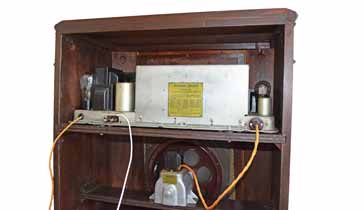
Philco 111 Vintage Radio
The Philco 111 vintage radio was an 11 vacuum tube radio that was introduced in 1931 to meet the market needs of the growing broadcast radio industry.
Philco Radios Includes:
Philco 111
Iconic radio receivers:
Summary of iconic radio receivers
Radio receiver history
Crystal radio sets
Development of the superhet radio
Radio history / timeline
The Philco 111 was an early vintage radio that was introduced as the broadcast radio market took off in the USA.
This antique radio represented a milestone in broadcast radio development and production - as a result it ended up being produced in large quantities.
The Philco 111 is seen occasionally in the antique radio markets and fairs, and even today it can work well.
Philco 111 basics
The radio was announced in January 1931 and was Philco's first superheterodyne radio. At the time, superhets were just starting to be introduced as the number of broadcast radio stations was increasing and considerably improved performance was needed for the discerning listener. The tuned radio frequency or TRF vintage radios could not provide the required performance under the ever more crowded ban conditions.
A further enabling factor in the use of the superhet principle was that Edwin Armstrong had lost a lawsuit where he wanted to prevent others from using his idea. With this lawsuit lost all could use the superheterodyne radio principle.
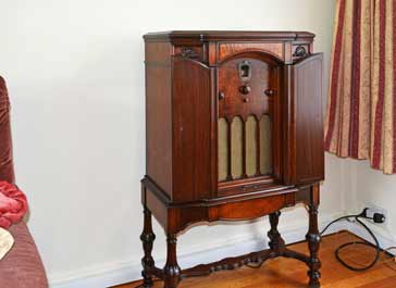
The Philco 111 was available in two versions. They were known as the "Highboy" and "Lowboy." The two radios were essentially the same radio but housed in different cabinet styles: the highboy being more elegant. However both were sizeable floor standing radios. The Highboy had double opening doors and was finished in an exotic wood.
The radio covered the medium wave band only because the long wave band used in Europe was not used in North America.
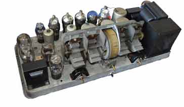
Philco 111 vacuum tube line-up
The Philco 111 radio had a total of 11 tubes - a figure unheard of in Europe where tubes of valves as they were called there were far more costly. Also the tubes were single function types, so one tube was required for each function and no reflex techniques were used, i.e. using a single tube to perform more than one function.
| Tube Line-up for Philco 111 Antique Radio |
||
|---|---|---|
| Valve Number | Type | Use within the circuit |
| 24 | RF amplifier tetrode | |
| 27 | Local oscillator | |
| 24 | Mixer / frequency conversion to intermediate frequency | |
| 24 | 1st IF amplifier | |
| 24 | 2nd IF amplifier | |
| 27 | Signal detector | |
| 27 | Detector amplifier | |
| 27 | Audio frequency amplifier | |
| 45 | Push pull power amplifier (one of two) | |
| 45 | Push pull power amplifier (one of two) | |
| 80 | Power input rectifier | |
* The Philco 111 circuit diagram did not have any part numbers given and therefore no valve reference numbers can be given in the first column of the table.
Tube types
Type 24 = screen tetrode
Type 27 = triode
Type 45 = power output triode
Type 80 = full wave rectifier
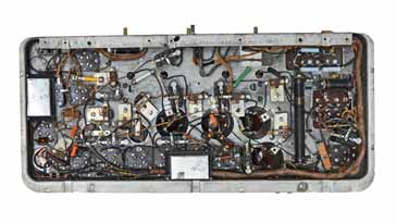
Philco 111 circuit description
The Philco 111 was an 11 valve superheterodyne broadcast radio. It was manufactured to high standards and gave a good quality of audio for the day.
As the signal enters this vintage radio, it follows a logical path through the circuit.
The signal enters and passes into an RF transformer where the secondary is tuned using one section of a four gang variable capacitor. It then passes into a second parallel tuned circuit to give additional RF selectivity to reduce images and precent front end overloading etc.
The signal then passes to the grid the first RF amplifier. This uses a Type 24 screen grid tetrode vacuum tube. This not only provides RF amplification to ensure a sufficient signal to noise ratio, but it also provides additional isolation to prevent the local oscillator leaking onto the antenna as well as the framework for the RF tuned circuits to give sufficient image rejection as well as preventing strong off channel signals from entering further into the radio.
Coupling to the next stage of the radio is achieved using a tuned transformer. This transformer is tuned using a section of the four gang variable capacitor to enable its resonant frequency to track the received frequency.
The local oscillator function is provided by a Type 27 triode vacuum tube. The output from this stage is inductively coupled from the resonant transformer used for the oscillator. This is then applied to the mixer stage along with the incoming RF signal.
The mixer uses another Type 24 screen grid tetrode to provide RF amplification as well as the mixing function.
The anode of the mixer tube has a fixed tuned IF transformer int he anode of the circuit to enable coupling to the IF stages.
The IF is at a frequency of 175 kc/s and it consists of two tubes providing IF gain, each uses a Type 24 tube. These stages are coupled using tuned IF transformers. They use trimmer capacitors to provide the frequency adjustment.
The signal from the intermediate frequency stages passes into a Type 27 tube stage acting as a detector. This is used to generate both the demodulated audio from the AM signal as well as a voltage dependent upon the carrier level to act as an automatic gain control, AGC, or was it was often reffed to in these early days as an automatic volume control, AVC. This voltage was applied to the earlier stages of the radio through the grid bias circuitry.
The audio from the detector is passed to another Type 27 tube which acted as a first stage audio amplifier. This lifted the audio signal level sufficiently to drive the final audio amplifier.
The final audio amplifier consists of two Type 45 power triode tubes ran in a push pull configuration. The audio drive signal from the previous stage was passed through a transformer with a centre tap on the output side to enable the audio to be split to drive the two tubes correctly. The output from the two output tubes was then passed into the output transformer, again with a centre tap, but this time on the input side to enable the signals from both tubes to be combined.
The power supply for the whole of this vintage radio was provided internally. It used a multi-section transformer providing a centre tapped HT winding to enable full wave rectification using the Type 80 rectifier tube. There were also separate wordings to give the required voltages for the heater supplies - a winding for all the Type 24 and Type 27 tubes, a winding for the Type 45 tubes and a third winding for the heater supply for the rectifier.
The use of a transformer for the line input was not always standard in these early days, but it reflects the high quality of the overall radio design and build.
The Philco 111 was a truly iconic vintage radio or antique radio - it is now nearly 100 years since it was first introduced. Its cabinet with opening door or doors and the legs on which it stood gave a true impression of quality - a factor that the radio lived up to in its operation.
 Written by Ian Poole .
Experienced electronics engineer and author.
More History:
Radio history timeline
History of the radio
Ham radio history
Coherer
Crystal radio
Magnetic detector
Spark transmitter
Morse telegraph
Valve / tube history
PN junction diode invention
Transistor
Integrated circuit
Quartz crystals
Classic radios
Mobile telecoms history
Vintage mobile phones
Return to History menu . . .


