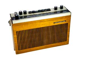
Tandberg TP41 Radio Receiver
The Tandberg TP41 is a vintage radio for broadcast reception that was introduced around 1971 and gained a name for a high quality audio and good overall performance.
Tandberg TP41 Radio Includes:
Tandberg TP41
TP41 circuit, block diagram & maintenance
Iconic radio receivers:
Summary of iconic radio receivers
Radio receiver history
Crystal radio sets
Development of the superhet radio
Radio history / timeline
The Tandberg TP41 broadcast radio was a classic radio of its era. Covering the Long, medium and short wave bands as well as the VHF FM band, it was an ideal portable radio providing quality audio.
Although it is not yet considered a full antique rado, it certainly comes under the classification of being a vintage radio, and it is a classic of its time.
This vintage radio comes in a deluxe wooden case and has a large internal loudspeaker as well as external sockets for low level audio, loudspeaker or headphones.
Coming from an era when portable radios did not offer anything much in the way of quality audio, this was a real, leader in terms of quality and made it a classic radio of its time.
As the TP41 radio is now typically around 50 years old and really high quality, it can be considered as a classic vintage radio.
Video: Tandberg TP41
Tandberg TP41 specification
The Tandberg TP41 offered a good overall specification for a transistor portable radio. There were apparently both European and US variants. Details of the specification for the European version are given below.
| Brief Specification for the Tandberg TP41 Broadcast Radio |
|
|---|---|
| Parameter | Specification |
| Basic description | Good quality transistor portable radio for broadcast reception on long medium, short and VHF FM wavebands. |
| Wavebands | Long wave: 150 - 269 kHz There are separate tuning controls for AM and FM. |
| Automatic Frequency Control, AFC | Use to ensure accurate tuning on FM. It can be switched off if required. |
| Fine tuning | The FM tuning control can be used for tine tuning on short wave. |
| Antenna | Ferrite rod antenna for long and medium wave. |
| Dial illumination | The dial is illuminated when the volume knob is depressed |
| Output power | 1.5W at 3% distortion (1.8W @ 10%) when operating on internal batteries. |
| Audio frequency range | 40Hz to 20 000 Hz |
| Tone controls | There are separate controls for the adjustment of bass and treble |
| Loudspeaker | Internal 5" x 9" 3.2 Ω ceramic magnet |
| Connections | DIN sockets for connection to: separate loudspeaker; mains power unit; tape recorder / record player. Minijack for headphones. |
| Diodes | 5 pcs |
| Transistors | 13 pcs |
| Power requirements | 9V from 6 x 1.5V flashlight cells [D-size]. |
| Current drain | 25mA at no output, 75mA at 50mW audio output and 295mA at full output. |
| Car adapter | A car adapter is incorporated into the bottom of the radio for inclusion into an automobile. (This is a type that is rarely seen these days.) |
| Dimensions | Length: 11", height: 7 1/8" (not including carry handle and knobs; depth: 3 ¼" |
| Weight (including batteries) | 5.5 lbs (2.5kg) |

There does appear to have been a version of the Tandberg TP41 manufactured for the US market. As long wave is not widely used there, the long wave band is substituted by a second short wave band.
Radio description and operation
The Tandberg TP41 vintage radio is generally intended for operation in an upright position when used in a normal domestic environment. The controls and tuning indication, etc are on the top, and there is a carry handle which can be angled up and over the panel for carrying. When the radio is in use, the handle can folded down so it does not obscure the panel.
On what may be considered to be the "lower part" of the panel includes the tuning dial. There are separate indications for the long, medium, and short wave bands and a second for the VHF FM band.
The volume control can be found on the left of the tuning dial, and when depressed this illuminates the dial lighting.
On the "top half" of the panel at the left hand end there is the telescopic antenna. This pulls out quite easily and extends to a reasonable length.
Moving along the top to the right, the next controls are the bass and treble controls. The action of these controls is very self explanatory and they give suitable lift and cut to the relevant sections of the audio spectrum.
It should be noted that the volume control includes a "loudness" function where the bass and treble are given a lift at low volumes.
In the centre of the top of the front or top panel there are the function and waveband switches. These are push button switches.
The left most one is the main ON / OFF button. Obviously when depressed it turns the radio on, and depressed again and the radio is turned off.
The centre button connects the external antenna for long and medium wave which is useful in a number of applications, especially when used in a car, or when an external antenna is needed to obtain better reception. The external antenna switch connects the telescopic antenna and the external socket for these bands. It is already connected for short wave and VHF FM.
The right most switch is the AFC. this is used on VHF FM to ensure the correct tuning. It is normally on, but of the switch is depressed then it is disabled.
The switches either side of the antenna switch are marked L and M for long and medium to the left of the antenna switch and S and FM for Short wave and VHF FM to the right. These are used to select the required waveband. When one switch is depressed, the previously depressed one pops up.
If both S and FM are depressed together then the auxiliary input on the circular DIN connector is enabled. In this way the radio can be used as an amplifier for tape recorder, etc.
To the right are the two tuning controls. One is marked L M S and this is the main tuning control for the long medium and short wave bands. The other is marked FM ΔS. On FM it is the main tuning dial and for short wave it provides fine tuning.
On the linear frequency "dial" there are markers which can be moved to indicate the position of favourite stations. This enables quick and easy tuning.
External connections
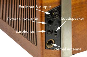
The connectors for the external connections on the Tandberg TP41 are located on the side of the radio. They are all contained within one moulded block which contains them all neatly.

There are five different connectors within the block on the side of the Tandberg TP41:
Headphones: A standard mono miniature jack is used for the headphones, but remember, as the radio came from t he 1970s and is only mono, so is the connection for the headphones.
Aux in & out: The auxiliary input and output is taken via the DIN circular audio connector. Inputs are only mono in view of the fact that the radio is mono, so there is one input and one output.
The Input is designed to accept a ceramic or crystal record pickup, or it can also be used for a line voltage input as well.
Auxiliary input and output connections for the Tandberg TP41 The output can be used to give audio to a larger amplifier or other audio equipment, and it is approximately line audio level.
External supply: There is a socket for an external supply. It is one of the standard types have concentric cylindrical conductors insulated from one another.
External loudspeaker: There is a DIN speaker socket for connecting an external loudspeaker. When a plug is plugged in it disconnects the internal loudspeaker.
Loudspeaker connections for the Tandberg TP41 The plugs are the DIN type intended for loudspeakers that have a flat conductor and a smaller cylindrical contact. These connectors were widely used on many vintage radios and other audio items from the 1970s but are not nearly as common these days.
The Tandberg TP41 radio is a classic of its time. Being around 50 years old now, it has certainly entered the vintage radio category, although it may not be quite considered an antique radio yet. However, it is still able to perform well and provide a listening experience which is better than many modern radios. Although many stations are closing their AM operations, the Tandberg TP41 still gives excellent performance on VHF FM where the quality of the sound can be enjoyed.
 Written by Ian Poole .
Experienced electronics engineer and author.
More History:
Radio history timeline
History of the radio
Ham radio history
Coherer
Crystal radio
Magnetic detector
Spark transmitter
Morse telegraph
Valve / tube history
PN junction diode invention
Transistor
Integrated circuit
Quartz crystals
Classic radios
Mobile telecoms history
Vintage mobile phones
Return to History menu . . .


