Tandberg TP41 Circuit & Maintenance
The Tandberg TP41 vintage radio worked well & had a straightforward format, but there are a few circuit issues that may require repair now.
Tandberg TP41 Radio Includes:
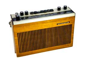
Tandberg TP41
TP41 circuit, block diagram & maintenance
Iconic radio receivers:
Summary of iconic radio receivers
Radio receiver history
Crystal radio sets
Development of the superhet radio
Radio history / timeline
The circuit for the Tandberg TP41 follows a reasonably familiar format for vintage transistor radios from around the 1970s. That said there are a few unusual elements to the design which are worth mentioning.
The circuit description and block diagram for the radio show that it is a superheterodyne radio which has an free running oscillators for the local oscillators as would be expected for the day and an IF which has tuned circuits for both 455 kHz and 10.7 MHz.
With a line up of thirteen transistors, five diodes, a component called a stabistor, and a 9 by 5 inch loudspeaker, the circuit for this this classic portable transistor radio provides a high level of performance for a transistor radio of its day.
Basic circuit description
The Tandberg TP41 often came with its own sheets defining the specification and it also provided a circuit diagram with the printed circuit board layout.
Nowadays the circuit diagram and printed circuit board layout are very useful as there are a few issues wit the circuit.
In essence the TP41 circuit uses a single superheterodyne format. There is a mixer oscillator for the long, medium and short wave bands and a separate tuner for VHF FM.
The output from the separate LF / MF tuner and VHF FM tuner is switched an applied to a common IF strip.
Signal demodulation uses a diode envelop detector for AM and an FM discriminator for FM.
The resulting audio is then applied to a four transistor audio amplifier.
AM Mixer oscillator circuit
The tuner section for the long medium and short wavebands is based around a single BC148 transistor that acts as RF amplifier, mixer and oscillator.
The input to this circuit stage comes from a ferrite rod could and capacitor asembly. Not only does the ferrite rod assembly provide RF selectivity, but it also acts as the antenna for medium and long wave reception. A separate coil and external antenna / telescopic antenna is used for the short wave bands because ferrite rods become lossy above frequencies of 2 MHz or so.
The self oscillating mixer approach is a very standard approach used within transistor broadcast radios and worked well considering the component count. However it does not, and cannot be expected to provide the high level of performance required for a professional communications receiver, but that is not what is needed here.
For the short wave bands, a level of bandspread is provided by using the VHF FM tuning control. This varies the coupling to a coil or loop for the relevant oscillator winding.
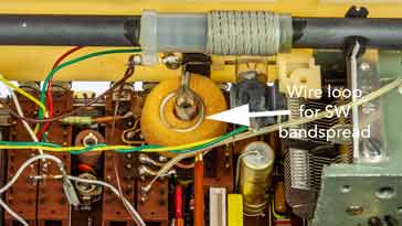
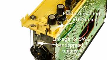
This is achieved using a mechanical link from the FM tuning to a single turn loop that sits over the tuning coil used for the short wave band. This loop compresses some foam plastic to remove vibrations and general unwanted movement, but allows the short wave tuning to be altered.
The output from this stage is then passed to the IF strip.
VHF FM tuner circuit
The VHF FM tuner circuit uses of three transistors and it is contained within a separate screened tin unit.
The RF amplifier is based around a BF200 transistor operation in common base mode to give gain, as well as isolation of the local oscillator from the antenna. Common base mode also has a relatively low input impedance which is ideal fort he nominally 75Ω input of any external antennas that will be fed with 75Ω coax, etc.
A BF195 transistor acts as the oscillator. Both the RF input and the local oscillator are permeability tuned.
A third transistor which is another BF195 acts as the mixer transistor. Its output is at 10.7 MHz which feeds into the IF amplifier.
IF amplifier circuit
Like many transistor portable vintage radios, the Tandberg TP41 uses dual IF transformers to enable the same transistor strip to act as a 455kHz as well as 10.7MHz amplifier.
The 10.7 MHz transformers are located closest to the collector of the transistors as they will have little effect at 455 kHz when this intermediate frequency is used.
Signal detection / demodulation circuits
Demodulator or detector circuits are required for both AM and wideband FM as both these modes of modulation need to have the modulation recovered from the signal.
The AM detector uses a single diode in a traditional envelope detector. The output is used for two purposes.
For the first the output is taken and then any RF on the output is removed using a simple CR network wit the cutoff frequency above the top audio frequency. This output is used to drive the audio amplifier.
A second feed is taken and fed into a CR network with a longer time constant. This buffered and then used as an automatic gain control which is used to control the agin of the IF stages. The AGC keeps the signal level approximately constant over a wide range of signal input levels. This helps maintain a more constant audio level at the output for a wide range of signal input levels.
For FM, the final IF drives a ratio detector type of FM discriminator. using a transformer arrangement and two diodes. Like the AM detector, two outputs are used.
The first has any remaining RF removed and is fed to the audio amplifier. A second output has a longer time constant to remove any audio and this is used as the automatic frequency control. This is used to keep the radio properly tuned into a stage, removing the effects of frequency drift. It acts upon the VHF FM oscillator which has a diode used as a varactor to give a small amount of frequency change.
TP41 audio circuits
The audio circuits for the Tandberg TP41 use a total of four transistors.A first stage based around a BC149 acts as a pre-amplifier and this drives a further transistor, a BC148 which acts as the driver for the output stage.
The output uses two germanium output transistors, one PNP and the other NPN. This complementary output enables a significant output level to be achieved. The transistors are germanium because of their lower turn on voltage and this helps to reduce cross-over distortion levels.
Accessing the Tandberg TP41 circuit board
Some people have had difficulty getting into the Tandberg TP41 vintage radio when they want to rectify faults or undertake any general maintenance, etc.
When taking the casing off the TP41, the first step is to remove the screws that hold the handle on.Once this has been done, the handle can be removed by gently easing it off the mounting points.
Once this has been done, the metal side elements can be slightly eased out at the top - just enough to let them clear the section of the wooden casing. They can then be slid downwards so that the element of the side bard that goes underneath the casing at the bottom comes out.
The next step is to remove the casing itself. The one at the front comes out most easily. It can be eased out at the bottom slightly and then pulled down. The other one requires pulling out a little more so that it can clear the plastic section that holds the connectors. It can then be slid down revealing the inner workings of the radio.
The speaker can be removed very easily by undoing the four screws holding it in place and then the connection wires can be slipped off the spade terminals on the speaker to completely free it up.
It is sometimes necessary to remove the top panel. This is clipped onto a light coloured plastic member holding all the tuning dial elements. First remove all the knobs by pulling them off. Then ease off the top panel carefully without breaking the white plastic member. Be aware that there is a plastic element or attachment that is associated with the VHF FM tuning. This holds some of the cord that enables the tuning to occur. It is best not to disturb this if at all possible. It is very easy for this to come off or break when removing the panel.
Maintenance issues
With any radio of this age, there are bound to be some issues. Over time, the patterns can be seen as similar faults occur in radios, and this is true of the Tandberg TP41.
Some of the issues that commonly occur with the TP41 are detailed below.
Stabistor failure: One of the more unusual aspects of the design of the radio is the incorporation of what is called a stabistor. It is D501 on the circuit diagram. This is an unusual device that provides a 1.5 volt stabilised voltage. This is used for the bias on the transistors in the RF and IF stages.
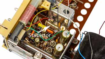
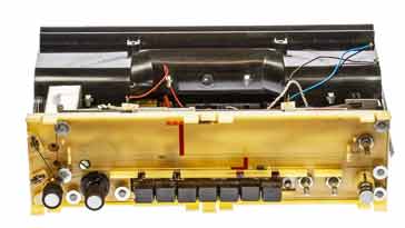
Tandberg TP41 printed circuit board showing the stabistor The stabistors are often reported as failing and leaving a white residue on the circuit board. Apparently this residue can harm the board, so it is wise to clean it off if this occurs.
The solution that is reported for these is to replace the stabistor with a network consisting of 2 silicon diodes and a germanium diode in series. These are used in forward conduction mode and as each silicon diode gives a drop of 0.6 volts and the germanium one gives 0.3 volts, this nicely equals 1.5 volts. It is also suggested that a 220 µF electrolytic capacitor is placed across to give good smoothing and ensure that no ripple or noise occurs on the line which might give instability.
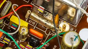
Close up view of Tandberg TP41 printed circuit board and the stabistor Interestingly this type of approach was used in the transistor portable model that followed the TP41.
There are several methods for replacing these stabistors that are seen on the Internet. As the radios in my possession have not yet exhibited this issue, the remedies have not been tried or tested here.
Output transistors: Another widely reported issue is that the output transistors can fail. These transistors are bolted to a heatsink along with their driver transistor. A little fiddly job but achievable with care. It is worth noting that the output transistors are germanium ones, although the drivers are silicon.
AM tuning control becomes stiff: On the two of these radios that I have worked upon, both have a stiff L M S or AM tuning control. Carefully taking off the top panel only reveals the mechanism with the dial mechanism. This is relatively complicated as strings are used for both the dial mechanisms and the cross over one another. It is wise not to disturb these if at all possible. Be very careful.
The reason for the issue is that the grease on the tuning knob dries and becomes solid over time. A few drops of white spirit can be suitably placed so that it seeps down to the bush. Give it a while to work, possibly over night and then gently turn it - it should start to move more easily. It may need a couple of attempts before it frees up sufficiently. Once it runs freely, a very sparing amount of oil can be used to keep it running smoothly. Don't put too much on it otherwise it may leak everywhere around the radio.
When a radio of this age is taken apart, there is bound to be dirt and grease that has accumulated over time. This can be very carefully removed and the exterior cleaned up to ensure that the radio looks its best. This type of issue is very common with all vintage radios and antique radios as well.
Although there are some common failures with these vintage radios, they are generally quite reliable and with the circuit information available from a variety of sites, they should not be too difficult to fix, if a little fiddly at times.
 Written by Ian Poole .
Experienced electronics engineer and author.
More History:
Radio history timeline
History of the radio
Ham radio history
Coherer
Crystal radio
Magnetic detector
Spark transmitter
Morse telegraph
Valve / tube history
PN junction diode invention
Transistor
Integrated circuit
Quartz crystals
Classic radios
Mobile telecoms history
Vintage mobile phones
Return to History menu . . .