
Vidor 254 Vintage Valve Radio
The Vidor 254 is a Long, Medium and Short waveband tuned radio frequency, TRF radio which dates from around 1936 and uses three valves for the radio and one for the power rectification.
Murphy Vintage Radio Equipment Includes:
Vidor 254 TRF
Iconic radio receivers:
Summary of iconic radio receivers
Radio receiver history
Crystal radio sets
Development of the superhet radio
Radio history / timeline
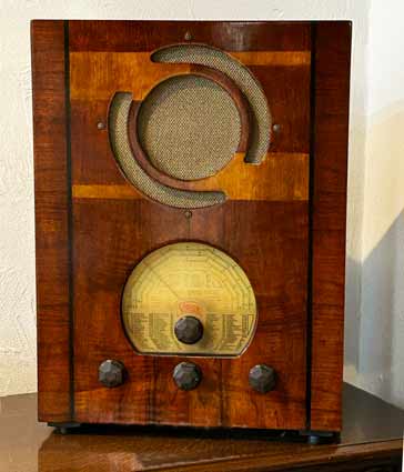
The Vidor 254 is a vintage broadcast radio that was introduced before WW2. Like many radios of the time it could operate on AC or DC, but this did mean that the chassis and other metalwork could become live.
The radio was finished in a very attractive two tone wooden case that was French polished veneered case.
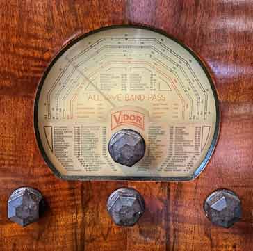
The radio gave good coverage, with a band for the long and medium wavebands as well as two short wave bands.
Vidor 254 specifications
The performance of the Vidor 254 was was what would be expected from a tuned radio frequency receiver, but nevertheless it was finished in a very nice case.
| Brief Specification for the Vidor 254 TRF Vintage Broadcast Radio |
|
|---|---|
| Parameter | Specification |
| Basic description | An AC / DC powered tuned radio frequency radio for the Long, Medium & Short wave bands |
| Date of Introduction | circa 1936 |
| Coverage | Long wave: 800 - 2000 Medium wave: 200 - 550 Short Wave 1: 48 - 145 Short Wave 2: 13.5 - 48.5 Coverage in metres |
Intermediate frequency | Not applicable |
| Loudspeaker | Electro Magnetic Dynamic LS (moving-coil with field excitation coil) |
| Power requirements | AC or DC mains of 200 - 250V |
| Valve complement | 3 valves for the radio section plus one for the power rectification |
| Case details | Wooden |
| Dimensions | 13.75 x 17.75 x 9.75 inch / 349 x 451 x 248 mm (w x h x d) |
Vidor 254 circuit description
The Vidor 254 follows a fairly traditional format for a tuned radio frequency, TRF radio of its day.
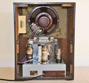
there are three valves used within the radio section, each of which is an appropriate form of pentode for the function being carried out.
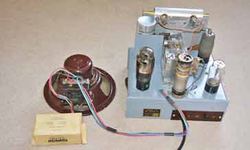
Courtesy Len Smyth
A further valve is used to provide half wave rectification or DC blocking for DC should the set be inadvertently connected to the wrong polarity.
| Vidor 254 Valve Line-Up |
||
|---|---|---|
| Valve Ident | Valve Type | Circuit Function |
| V1 | VP1321 | RF, amplifier pentode |
| V2 | SP13C | Pentode - regenerative detector |
| V3 | PEN 36C | Audio amplifier & audio output |
| V5 | ID5 - half wave rectifier | Power rectification |
The signal from the aerial enters via a variable capacitor to provide antenna trimming and this can be shorted is required. The signal then passes through an isolating capacitor to ensure that any voltage on the chassis, etc does not reach the antenna.
This links to the input bandpass filter for the medium and lon wavebands, and for the short wave bands only a coupling coil is used.
These filters and coupling coils pass the signal to the RF amplifier pentode.
The second valve, V2 takes the signal from the RF amplifier and this is used to provide detection. Reaction or regeneration is also used to improve the gain and selectivity.
Courtesy Len Smyth
The Output from the regenerative detector stage based around V2 is passed to the output stage based around V3. The signal is then converted into audible vibrations using an energised moving coil loudspeaker - this is effectively a loudspeaker that has an electromagnet rather than a permanent magnet. It was a technique that was very common in early radios.
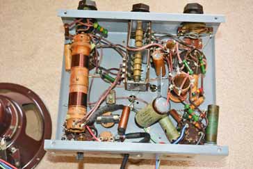
The power supply uses a voltage dropper resistor to provide the low voltage requirements for the radio set.
The incoming power, is rectified using a half wave rectifier, and this also acts as a series diode for DC preventing incorrectly polarised voltage being applied tot he radio which would damage the electrolytic capacitors.
Courtesy Len Smyth
The half wave rectified power is applied to a filter consisting to electrolytic capacitors and a series inductor for the loudspeaker energising.
The Vidor 254 was a neat small radio that performed adequately for its day. Being a tuned radio frequency radio, it was old technology whereas the newer and higher performance radios were using superheterodyne techniques.
With the increasing number of broadcast stations becoming active, the interference levels were rising and especially at night when the radio propagation conditions would bring in stations from further afield, interference would have been a problem.
However the Vidor 254 was a lower cost radio and its appearance would have meant that would have been able to grace the best living rooms of the day.
 Written by Ian Poole .
Experienced electronics engineer and author.
More History:
Radio history timeline
History of the radio
Ham radio history
Coherer
Crystal radio
Magnetic detector
Spark transmitter
Morse telegraph
Valve / tube history
PN junction diode invention
Transistor
Integrated circuit
Quartz crystals
Classic radios
Mobile telecoms history
Vintage mobile phones
Return to History menu . . .


