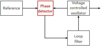
The phase detector is a key element of a phase locked loop and many other circuits. There are several types ranging from digital to analogue mixer and more.
The phase sensitive detector can be used in a number of circuits – anywhere that it is necessary to detect the phase between two signals.
One of the main areas where phase detectors are used is within phase locked loops, although this is by no means the only one.
The phase detector enables phase differences to be detected and the resultant "error" voltage to be produced.
There are different types of phase detector. They can be categorised in a variety of ways, but one is given below:
Phase only sensitive detectors
Phase / frequency detectors
Phase sensitive and phase-frequency detectors can be used in different ways and they are therefore described separately.
Phase only sensitive detectors
Phase detectors that are only sensitive to phase are the most straightforward form of phase detector. As the name indicates their output is only dependent upon the phase difference between the two signals. When the phase difference between the two incoming signals is steady, they produce a constant voltage. When there is a frequency difference between the two signals, they produce a varying voltage at a frequency equal to the frequency difference.
The difference frequency product is the one used to give the phase difference.
However it is quite possible that the difference frequency signal will fall outside the pass-band of the loop filter, and hence the overall phase locked loop. If this occurs then no error voltage pass through the PLL loop filter and on to the Voltage Controlled Oscillator, VCO, to bring it into lock. This means that there only is a limited range over which the phase locked loop can be brought into lock. This range is called the capture range. Once in lock the loop can generally be pulled over a much wider frequency band.
Apart from using a phase frequency detector, there are several ways in which this problem can be overcome. The oscillator must be steered close to the reference oscillator frequency. This can be achieved in a number of ways. One is to reduce the tuning range of the oscillator so that the difference product will always fall within the pass-band of the loop filter. In other instances another tune voltage can be combined with the feedback from the loop to ensure that the oscillator is in the correct region. This is approach is often adopted in microprocessor systems where the correct voltage can be calculated for any given circumstance.
Several forms of phase only sensitive phase detectors exist:
Double balanced mixer phase detector: The double balanced mixer or diode ring mixer is one of the simplest forms of phase detector. The double balanced mixer of diode ring phase detector is a simple and effective form of phase detector that can be implemented using a standard diode ring module.
Diode ring or double balanced mixer used as a phase detector
The mathematic shows that the voltage at the IF port of the diode ring mixer varies as the cosine of the phase different between the inputs ta the RF and LO inputs to the diode ring. This means that null or 0V readings are obtained for a zero degree phase difference, but also at odd multiples of π/2. Maximum and minimum voltages are seen at points where the phase difference is a multiple of π. Diode ring phase detector response curve
XOR phase detector: The exclusive OR, XOR phase detector circuit can provide a very useful simple phase detector for some applications. It comprises of a logic exclusive OR circuit. Being digital in format it can often fit into a phase locked loop with ease as many of the circuits associated with the phase locked loop may already be in a digital format. Alternatively an exclusive OR can be made from discrete components to give a wider variety of levels and other options. Exclusive OR phase detector
The way in which an exclusive OR, XOR phase detector works can be seen by the diagram below: XOR phase detector response waveforms
It can be seen that using these waveforms, the XOR logic gate can be used as a simple but effective phase detector.
As might be expected for such a simple circuit, there are a few drawbacks to using an XOR phase detector:
The phase detector is sensitive to the clock duty cycle. This means that a steady duty cycle, i.e. 1:1 should be used. It will lock with a phase error if the input duty cycles are not 50%.
The output characteristic of the XOR phase detector show repetitions and gain changes. This means that if there is a frequency difference between the input reference and PLL feedback signals the phase detector can jump between regions of different gain. The characteristic of the phase detector is as shown below: XOR phase detector response curve
The nominal lock point with an XOR phase detector is also at the 90° static phase shift point.
Unlike an analogue mixer phase detector, the XOR version is independent of input amplitude and constant over a π phase range.
Phase-frequency detectors
Another form of detector is said to be phase-frequency sensitive. These circuits have the advantage that whilst the phase difference is between ±180° a voltage proportional to the phase difference is given. Beyond this the circuit limits at one of the extremes. In this way no AC component is produced when the loop is out of lock and the output from the phase detector can pass through the filter to bring the phase locked loop, PLL, into lock.
There are several types of phase-frequency detectors that can be used.
Edge triggered JK flip flop phase frequency detector: This form of phase comparator or phase detector is used in some designs.
JK Flip Flop
The idea behind the JK flip flop based comparator is that it is a sequentially based circuit and this can be used to provide two signals: one to charge, and one to discharge a capacitor.
Often when using this form of phase detector, an active charge pump is recommended.
JK Flip Flop States
v1
v2
Qn+1
0
0
Qn
0
1
0
1
0
1
1
1
Qn bar
JK Flip Flop phase detector waveforms
These waveforms can be interpreted and it is found that the overall response appears as below.
JK flip flop phase detector response
Dual D type phase comparator: This type of phase frequency detector is widely used in many circuits because of its performance and ease of design and use. The phase detector is based around two D type flip flops and an NAND gate, although there are a number of slightly different variants.
The circuit for the dual D-type phase comparator operates by comparing the reference and VCO signals which enter the clock inputs, one on each D-type. The NAND gate output is fed to the reset, R, inputs of both D-types. The inputs to the NAND gate are taken from the Q outputs and the output to the loop filter being taken from one of the Q outputs. Dual D-Type phase detector circuit
Obviously various configurations using Q outputs, Q-bar outputs and AND gates are possible, but for simplicity sake the version using the Q outputs from the D-types and using a NAND gate is shown.
Phase detector dead zone
One of the issues that faces the designers of very low phase noise synthesizers and phase locked loops, is a phenomenon referred to as the phase detector dead zone.
This occurs where digital phase detectors are used. It is found that when the loop is in lock and there is a small phase difference between the two signals, very short pulses are created by the phase detector logic gates. Being very short, these pulses may not propagate and add charge into the charge pump / loop filter. As a result the loop gain is reduced and this forces up the loop jitter / phase noise.
Phase detector output characteristic showing dead zone
To overcome this one solution is to add a delay in the phase detector reset path, i.e. on the output of the NAND gate in the dual D-type detector before the reset terminals of the D-types. This forces a minimum pulse length. Another solution is to add a small amount of leakage across the loop filter so that the charge pump has to supply current even when the loop is in lock.
There is a good choice of the type of phase detector that can be used within a phase locked loop. For many synthesizer applications variants of the dual D-type approach are widely used, as are sample and hold phase detectors. The analogue approaches have the disadvantage that they are only phase sensitive and not phase frequency sensitive and therefore the loop bandwidth can be an issue in terms of gaining lock.
Written by Ian Poole . Experienced electronics engineer and author.
Quote:Although human subtlety makes a variety of inventions by different means to the same end, it will never devise an invention more beautiful, more simple or more direct than does nature, because in her inventions nothing is lacking, and nothing is superfluous. Leonardo da Vinci.
Point to ponder: Professor Sir Ambrose Fleming the inventor of the diode valve was an eccentric. He was often heard whistling the letter "V" in Morse code through his teeth as this was this was the letter he used for his radio transmitter test messages.


 Written by Ian Poole .
 Check out my online shop with our own downloadables and coffee mugs, etc, and also a huge number of electronics products from our selected suppliers.