The performance of the voltage controlled oscillator in any phase locked loop is a key circuit block, determining many aspects of the overall performance.
Within a phase locked loop, PLL, or frequency synthesizer, the performance of the voltage controlled oscillator, VCO is key.
The voltage controlled oscillator performance governs many aspects of the performance of the whole phase locked loop or frequency synthesizer. Accordingly careful design is necessary.
The design of a high performance voltage controlled oscillator, VCO, is not is not a trivial task. Consideration of the circuit, components used and the layout all play a role in determining the performance. This requires sound theoretical design, followed by careful choice of all the components and then a good PCB layout. Even with circuit simulation, it may take a couple of iterations of the VCO layout .
VCO requirements
When designing a voltage controlled oscillator, VCO, there are several parameters that must be considered before the design starts. These define the key performance parameters needed for the VCO.
VCO tuning range: It is obvious that the voltage controlled oscillator must be able to tune over the range that the loop is expected to operate over. This requirement is not always easy to meet and may require the VCO or resonant circuit to be switched in some extreme circumstances.
VCO tuning gain: The gain of the voltage controlled oscillator is important. It is measured in terms of volts per Hz (or V/MHz, etc). As implied by the units it is the tuning shift for a given change in voltage. The voltage controlled oscillator gain affects some of the overall loop design considerations and calculations.
Voltage controlled oscillator V/f curves
The VCO response curves can be seen to be relatively straight at lower frequencies. However they normally flatten out at higher voltages where the changes in capacitance from the varactor diodes reduce.
VCO V/f slope: It is a key requirement for any voltage controlled oscillator used in a phase locked loop that the voltage to frequency curve is monotonic, i.e. it always changes in the same sense, typically increasing frequency for increasing voltage. If it changes, as can happen in some instances normally as a result of spurious resonances, etc, this can cause the loop to become unstable. Accordingly, this must be prevented if the phase locked loop is to operate satisfactorily.
Voltage controlled oscillator V/f curve with discontinuity
This curve shows a small dip and would result in the phase locked loop becoming unstable.
Phase noise performance: The phase noise performance of the voltage controlled oscillator is of particular importance in some PLL applications - particularly where they are used in frequency synthesizers. The phase noise performance of the voltage controlled oscillator is the dominant factor of phase noise outside the PLL loop bandwidth. Although close in noise is reduced by the action of the PLL, outside the loop bandwidth there is no reduction of VCO phase noise.
These are some of the main requirements that need to be known from the outset of the design of the VCO. Careful optimisation of the Q of the tuned circuit, especially using varactor diodes with as high a Q as possible, choice of active device, optimisation of the feedback within the oscillator.
VCO feedback
Like any oscillator, a VCO may be considered as an amplifier and a feedback loop. The gain of the amplifier may be denoted as A and the feedback as B.
For the circuit to oscillate the total phase shift around the loop must be 360° and the gain must be unity. In this way signals are fed back round the loop so that they are additive and as a result, any small disturbance in the loop is fed back and builds up. In view of the fact that the feedback network is frequency dependent, the build-up of signal will occur on one frequency, the resonant frequency of the feedback network, and a single frequency signal is produced.
Many oscillators and hence VCOs use a common emitter circuit. This in itself produces a phase shift of 180°, leaving the feedback network to provide a further 180°.
Other oscillator or VCO circuits may use a common base circuit where there is no phase shift between the emitter and collector signals (assuming a bipolar transistor is used) and the phase shift network must provide either 0° or 360°.
For the oscillator to oscillate on a given frequency, the system includes a resonant circuit to ensure that the oscillation occurs on a given frequency. The resonant circuit can be one of a number of configurations from an LC resonant circuit in either series or parallel resonance dependent upon the circuit, or a quartz crystal, etc.
Colpitts & Clapp VCO circuits
Two commonly used formats for the VCO are the Colpitts and Clapp oscillator circuits. Of the two, the Colpitts circuit is the most widely used, but both are very similar in their configuration.
These circuits operate as oscillators because it is found that a active device such as a bipolar transistor with capacitors placed between the base and emitter (C1) and the emitter and ground (C2) fulfils the criteria required for providing sufficient feedback in the correct phase to produce an oscillator. For oscillation to take place the ratio C1 : C2 must be greater than one.
The resonant circuit is made by including a inductive element between the base and ground. In the Colpitts circuit this consists of just an inductor, whereas in the Clapp circuit an inductor and capacitor in series are used.
The conditions for resonance is that:
The capacitance for the overall resonant circuit is formed by the series combination of the two capacitors C1 and C2 in series. In the case of the Clapp oscillator, the capacitor in series with the inductor is also included in series with C1 and C2.
Thus the series capacitance is:
In order to make the oscillator tune it is necessary to vary the resonant point of the circuit. This is best achieved by adding a capacitor across the indictor in the case of the Colpitts oscillator. Alternatively for the Clapp oscillator, it can be the capacitor in series with the inductor.
For high frequency applications a circuit where the inductive reactance is placed between the base and ground is often preferred as it is less prone to spurious oscillations and other anomalies.
Choice of VCO active device
It is possible to use both bipolar devices and FETs within a VCO, using the same basic circuit topologies. The bipolar transistor has a low input impedance and is current driven, while the FET has a high input impedance and is voltage driven. The high input impedance of the FET is able to better maintain the Q of the tuned circuit and this should give a better level of performance in terms of the phase noise performance where the maintenance of the Q of the tuned circuit is a key factor in the reduction of phase noise.
Another major factor is the flicker noise generated by the devices. Oscillators are highly non-linear circuits and as a result the flicker noise is modulated onto VCO as sidebands and this manifests itself as phase noise. In general bipolar transistors offer a lower level of flicker noise and as a result VCOs based around them offer a superior phase noise performance.
VCO tuning
To make a VCO, the oscillator needs to be tuned by a voltage. This can be achieved by making the variable capacitor from varactor diodes. The tune voltage for the VCO can then be applied to the varactors.
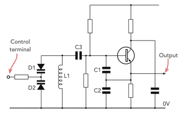
Voltage controlled oscillator circuit
It will be noticed that the control line from the phase detector is isolated from the varactor diodes using a resistor. RF chokes do not work well as they become part of the resonant circuit and tend to introduce the possibility of spurious resonances and non-monotonic V/f curves. Resistor values around 10kΩ often work well. Much lower than this and insufficient RF isolation is provided and this can lower the Q of the tuned circuit; much higher than this and the source impedance may be too high. A little experimentation may be needed to find the optimum value.
The series capacitor C3 is used to block the DC from the inductor otherwise it would provide a direct short to ground and upset the bias arrangements of the circuit. Its value is normally large in comparison with C1 and C2 and can be ignored from the resonance perspective.
VCO varactor issues
When varactor diodes are used within a voltage controlled oscillator, care must be taken in the design of the circuit to ensure that the drive level in the tuned circuit is not too high. If this is the case, then the varactor diodes may be driven into forward conduction, reducing the Q and increasing the level of spurious signals.
There are two main types of varactor diode that may be used within a VCO - the names refer to the junction within the diode and this affects their performance.
Abrupt : As the name indicates, abrupt diodes, have a relatively sharp transition between the areas of the diode. While abrupt varactor diodes do not offer such a high tuning range or linear transfer characteristic they are able to offer a higher Q than their hyper-abrupt cousins. This results in a better voltage controlled oscillator phase noise performance. The other point to note is that abrupt varactor diodes may need a high tuning voltage to provide the required tuning range, as some diodes may require a tuning voltage for the VCO to vary up to 50 volts or slightly more. This may create issues in providing a voltage supply with a sufficiently high voltage for the drive circuits.
Hyper-abrupt : Hyper-abrupt diodes have a relatively linear voltage : capacitance curve. As a result they offer a very linear tuning characteristic that may be required in some applications. They are also able to tune over a wide range, and may typically tune over an octave range with less than a 20 volt change in tuning voltage. However they do not offer a particularly high level of Q. As this will subtract from the overall Q of the tuned circuit this will mean that the phase noise performance is as good as that which can be obtained using an abrupt varactor diode.
Voltage controlled oscillator design is far from trivial despite the apparent simplicity of the circuit. Often a design will need careful optimisation of the feedback levels combined with the device and layout. The design of the VCO will need to carefully balance the needs of often conflicting requirements like wide tuning range and low phase noise.
Once the design has been fully optimised and the design completed, the levels of performance that can be achieved are remarkably good.
Written by Ian Poole . Experienced electronics engineer and author.
Fact of the day: It was on this day in 1835 that Elisha Gray was born in Barnesville Ohio. He started a small company to make telegraphic equipment. This eventually became the Western Electric Company. He also claimed to have invented the telephone in the 1870s, but lost the patent rights to Alexander Graham Bell in a case eventually decided in the U.S. Supreme Court.
Quote:For to be free is not merely to cast off one\'s chains, but to live in a way that respects and enhances the freedom of others. Nelson Mandela
Point to ponder: If an experiment works, something has gone wrong.


 Written by Ian Poole .