RF Combiners, Splitters, Couplers and Hybrids
RF splitters combiners, couplers and hybrids are a group of components used in many RF applications.
Home » Radio & RF technology » this page
RF Combiner Splitter Couplers & Hybrids Includes:
Combiner, splitter, coupler hybrids overview
Splitters & Combiners
Resistive splitter & combiner
Hybrid splitter & combiner
Wilkinson splitter & combiner
Directional coupler
RF combiners, splitters, couplers and hybrids are circuit elements that are used in many RF applications to split, combine or sample RF power. Typically they are passive devices that can be used within RF circuits, or even externally.
As the RF combiners, splitters, couplers and hybrids are very similar in nature, they are often linked together in explanations or within similar areas within manufacturers catalogues.
RF coupler, splitter, combiner, hybrids - what they are
The terms RF combiners, splitters, couplers and hybrids refer to slightly different items. Each item is used in RF design and all are important to the RF designer.
- RF combiner: An RF combiner is used to combine RF from a number of different sources. This is achieved while maintaining the characteristic impedance of the system. Dependent upon the type of combiner it may introduce additional loss by using resistors, or it may be use transformers in which case it could in theory be lossless.
RF combiners can be used in a number of different applications. They are used for sending several signals along a single feeder, and they may also be used for circuits where several RF signals need to be brought together. . . . . Read more about the Combiner. - RF splitter: An RF splitter is the reverse of a combiner - in fact splitters and combiners utilise exactly the same circuits - the inputs for one form the outputs for the other. As the signal is split a number of ways, there is an associated reduction in signal level between the input and the output dependent upon the number of outputs for which the signal is shared. . . . . Read more about the Power Splitter / Divider.
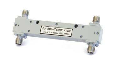
- RF directional coupler: Directional couplers have many similarities with splitters. They are often used to sample signals and they may have directional properties. Rather than being based upon transformer technology they use capacitive coupling to achieve their aims. As the name implies a key feature of directional couplers is that they only couple power flowing in one direction. Power entering the output port is coupled to the isolated port but not to the coupled port.
- RF hybrid: A number of circuits are referred to as hybrids. RF hybrids are based on transformers, and as such RF splitters or RF combiners may be referred to as hybrids when they use transformer technology rather than just resistive technology. This gives many advantages, dependent upon the actual circuit, but one of the main ones is that hybrids do not have the resistive losses of the resistive ones.
Circuit symbols
The circuit symbols for combiners, splitters, couplers and hybrids are not as widely used as some of the more commonly used symbols for semiconductors, and other passive components. As a result the splitter & divider symbols along with those for couplers tend to be less standardised.
The splitter / divider and combiner symbols used below are some of the more commonly used versions seen.
One of the more widely used circuit symbols is that of the power divider / splitter.

The splitter / divider symbol is very self explanatory. Power enters the divider at port P1 and is split two ways. It is obviously possible to have power split more than two ways and the symbol would represent this.
As a reminder that there is a reduction in power level as a result of the split, sometimes the loss is stated. A two way power splitter has a 3dB reduction in power between P1 and P2 or P3 even if there are no resistive or other losses resulting in power dissipation.

The combiner symbol is just the reverse of the splitter symbol.

Directional coupler symbols are rather different to the splitter and combiner symbols.
The directional coupler circuit symbols indicate more about the coupling, and the actual coupler symbol used depends upon the form of coupler and the way it needs to be shown.

In this directional coupler, power entering port 1 is coupled to the transmitted port and a small amount, in this case -15dB as shown is coupled to Port 3. Often the level of coupling is shown on the coupler symbol.
Directional couplers are frequently symmetrical so there also exists port 4, which is named the isolated port. A portion of the power applied to port 2 will be coupled to port 4. However, the device is not normally used in this mode and port 4 is usually terminated with a matched load (typically 50 ohms). This termination can be internal to the device and port 4 is not accessible to the user. Effectively, this results in a 3-port device, hence the utility of the second symbol for directional couplers.
The four port directional coupler circuit symbol is shown below.

Although they are not used as widely as some other RF components, splitters, combiners, couplers and hybrids are still particularly useful. They may often be made from discrete components, sometimes embedded in an RF design, although connectorised units may also be bought, especially where their frequency range extends into the microwave region.
 Written by Ian Poole .
Experienced electronics engineer and author.
More Essential Radio Topics:
Radio Signals
Modulation types & techniques
Amplitude modulation
Frequency modulation
OFDM
RF mixing
Phase locked loops
Frequency synthesizers
Passive intermodulation
RF attenuators
RF filters
RF circulator
Radio receiver types
Superhet radio
Receiver selectivity
Receiver sensitivity
Receiver strong signal handling
Receiver dynamic range
Return to Radio topics menu . . .