Envelope Tracking Delay Balancing & Synchronisation
Delay balancing is required within envelope tracking to ensure that the peaks and troughs of the RF amplitude synchronise the voltage waveform applied to the RF power amplifier.
Home » Radio & RF technology » this page
Envelope Tracking primer includes:
What is envelope tracking
Block diagram
PSU / DC modulator
Envelope shaping
Control signal
Delay balancing
It is necessary to match the delays that occur within the arms or circuit paths of the envelope tracking system, otherwise there will be a mismatch in the delivery of the required voltage to the power amplifier.
Impact of poor envelope tracking synchronisation
It is particularly important to have good synchronisation between the RF envelope and the control signal otherwise the RF amplifier performance will be degraded:
- Increased power dissipation: If there is poor synchronisation between the waveforms then power dissipation will be increased because the voltage peaks will not occur at the same time as the RF envelope peaks, resulting in increased power dissipation
- Reduced efficiency: The increased power dissipation reflects into the overall operation of the amplifier as a reduction in efficiency.
- Increased distortion: Poor synchronisation will also mean that there will be insufficient voltage supplied to meet the envelope peaks and this will result in the signal driving the amplifier into compression, thereby distorting the signal
Delay mismatches
In order to understand the reason for the envelope tracking delay balancing it is necessary to look at the reasons why delay mismatches occur.
The reasons for the mismatch in the RF envelope and the envelope tracking signal arise from the different delay periods that occur in the paths taken by the two signals.
Looking at the block diagram, it can be seen that there are two distinct signal paths within the envelope tracking signal: one for the RF signal and another for the envelope control signal..

In this diagram, it can be seen that the I and Q signals enter a block called delay where the delay matching can be applied and they are also split off along their different paths.
The RF path passed into DACs, one for the I and another for the Q signal and these outputs are then filtered and mixed up to the required frequency where they are summed and then amplified.The envelope control signal path incorporates very different signal processing techniques and therefore it has a different level of delay.
The envelope control signal path incorporates a number of different baseband blocks to ensure the contour of the control signal is correct: this involves aspects including gain control and a RAM look up table. The signal is converted from digital into an analogue format and then filtered before being applied to the envelope tracking supply.
One of the major factors in the different delays between the two signal paths is the low pass filters used after the DACs. Low pass filters inherently have a delay and as their characteristics are very different, they have different levels of delay.
As seen on the left most block in the block diagram, the delay balanced is added as the IQ signals are split along the two paths and in this way the delay can easily be balanced at the outset.
Envelope tracking synchronisation examples
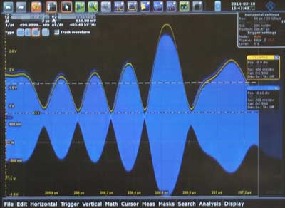
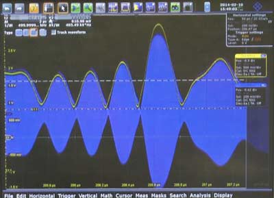
In order to illustrate the issue of synchronisation it is useful to see some examples.
There are images taken from real laboratory envelope tracking systems showing good and poor synchronisation levels.

If the delay envelope tracking balancing is not well matched, both signals fall out of synchronism and there is a mismatch between the two signals.
As a rough rule of thumb the alignment must be within about half a nanosecond for 20 MHz bandwidth LTE signal.

Even though the apparent discrepancy appears small, there are areas where there is insufficient voltage applied to the RF amplifier to cater for the signal, and other areas where there is too much voltage which will result in excess dissipation.
 Written by Ian Poole .
Experienced electronics engineer and author.
More Essential Radio Topics:
Radio Signals
Modulation types & techniques
Amplitude modulation
Frequency modulation
OFDM
RF mixing
Phase locked loops
Frequency synthesizers
Passive intermodulation
RF attenuators
RF filters
RF circulator
Radio receiver types
Superhet radio
Receiver selectivity
Receiver sensitivity
Receiver strong signal handling
Receiver dynamic range
Return to Radio topics menu . . .


