GPIB Pinouts & Interconnections
Information and data for IEEE 488 or GPIB pinouts or pin allocations used for GPIB inter-connections.
GPIB / IEEE 488 Bus Includes:
GPIB / IEEE 488 bus
GPIB operation / commands / protocol
IEEE 488.2
How to Use GPIB / IEEE 488
GPIB / IEEE 488 cables
GPIB / IEEE 488 connectors
GPIB / IEEE 488 pinout / pin connections
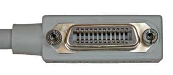
The connections or pinout for the GPIB system is standardised and uses the 24 way Amphenol Type 57 connector.
While some systems have, mainly in the past, used other connectors, the 24 way Amphenol type 57 connector is the one that is by far the most widely used and its connections have been defined as in the table given below.
The GPIB pinout is therefore well standardised and virtually without exception the Amphenol style connector is the one used these days.
GPIB connector pins numbering
The diagram below shows the various pins on the standard 24 way Amphenol type 57 connector in order to identify the different pins for the pinout with their relevant functions.
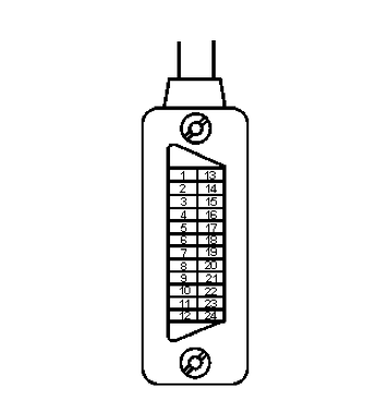
It is worth noting that the actual pin numbers are written onto the plastic of the connector by the pins themselves. This is always worth checking to make sure orientations are correct and to eliminate errors in interpretation.
GPIB pinout connections
The connections or pinout for the GPIB connector are given in the table below:
| GPIB Pinout Table | ||
|---|---|---|
| GPIB Pin No |
GPIB Line Name |
GPIB Abbreviation |
| 1 | Data Input / Output 1 | DIO1 |
| 2 | Data Input / Output 2 | DIO2 |
| 3 | Data Input / Output 3 | DIO3 |
| 4 | Data Input / Output 4 | DIO4 |
| 5 | End or Identify | EOI |
| 6 | Data Valid | DAV |
| 7 | Not Ready For Data | NRFD |
| 8 | Not Data Accepted | NDAC |
| 9 | Interface Clear | IFC |
| 10 | Service Request | SRQ |
| 11 | Attention | ATN |
| 12 | Shield (Connected to Earth) | |
| 13 | Data Input / Output 5 | DIO5 |
| 14 | Data Input / Output 6 | DIO6 |
| 15 | Data Input / Output 7 | DIO7 |
| 16 | Data Input / Output 8 | DIO8 |
| 17 | Remote Enable | REN |
| 18 | Twisted pair with pin 6 | |
| 19 | Twisted pair with pin 7 | |
| 20 | Twisted pair with pin 8 | |
| 21 | Twisted pair with pin 9 | |
| 22 | Twisted pair with pin 10 | |
| 23 | Twisted pair with pin 11 | |
| 24 | Signal Ground | |
It can be seen from the pinout table for the GPIB connections that the DAV, NRFD and NDAC handshaking lines all run with twisted pairs as do IFC, SRQ and ATN.
Again it can be seen from the pinout table that the GPIB connections for the data lines do not have twisted pairs, but are contained within the overall screening of the cable.
 Written by Ian Poole .
Experienced electronics engineer and author.
More Test Topics:
Data network analyzer
Digital Multimeter
Frequency counter
Oscilloscope
Signal generators
Spectrum analyzer
LCR meter
Dip meter, GDO
Logic analyzer
RF power meter
RF signal generator
Logic probe
PAT testing & testers
Time domain reflectometer
Vector network analyzer
PXI
GPIB
Boundary scan / JTAG
Data acquisition
Return to Test menu . . .