
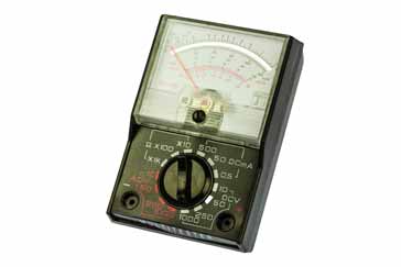
How an Analogue Multimeter Works
The analogue multimeter is based around the use of a moving coil meter to which seires and parallel resistors are added - this enables the meter to measure a wide range of values for both voltage and current.
Multimeter Tutorial Includes:
Test meter basics
Analogue multimeter
How does an analogue multimeter work
DMM digital multimeter
How a DMM works
DMM accuracy & resolution
DMM CAT ratings
How to buy best digital multimeter
Cheap vs expensive DMM
How to use a multimeter
Voltage measurement
Current measurements
Resistance measurements
Diode & transistor test
Fault finding transistor circuits
Analogue vs Digital multimeter
Test leads & probes
Analogue multimeters are a form of test instrument that is widely used today, even though digital multimeters are much more widely available.
In order to be able to get the most from an analogue test meter, like any test instrument, it helps to have a good understanding of how it works.
These analogue test meters are based around the use of a moving coil meter. In order to provide the variety of test ranges needed for the test instrument, additional precision value resistors are added either in series of parallel according to the requirement to measure voltage of current. A slightly different configuration is needed for measuring resistance.
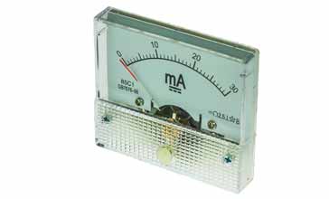
Moving coil meter
The moving coil meter is at the core of analogue multimeters and also a variety of other items of analogue test equipment as well.
There are several types of electrical meter that are available, but the type most suited to test meters and many other types of test equipment is the moving coil meter.
Electrical meters use the fact that a current flowing in a wire or coil generates a magnetic field. This field can be used to deflect a meter needle such that the size of the current is indicated by the degree of deflection.

As the name suggests, the moving coil meter uses a light weight coil that is pivoted and attached to a meter needle. It is held within the magnetic field provided by a fixed magnet. As current flows through the coil, so a magnetic field is built up and this interacts with the field from the fixed magnet and a force is exerted upon the coil so that it turns and moves the meter needle that is attached to the coil.
A hair spring is also attached to the moving coil so that the deflection is restrained and hence the deflection is proportional to the force provided by the coil, and hence to the current flowing.
In this way, it can be seen that the moving coil meter measures the level of current flowing in a circuit. Altering the number of turns on the coil, the magnetic strength and other parameters can change its range. They can also only measure direct current.
In concept the idea is straightforwards, but the meter is actually a relatively precision item, although as they are mass produced for many test instruments as well as many other electronic gadgets and equipment, the moving coil meters can be made relatively easily and cheaply.
It is worth noting that most moving coil meters have a small adjusting screw attached to the spring so that the meter can be zero'ed when no current is flowing. Changes in attitude of the meter can change the balance of the system meaning that it may not sit at zero correctly when no current is flowing. The adjuster interacts with the coil spring to set the position correctly.
Moving coil meters are normally specified in terms of the current required to give full scale deflection, FSD, and the coil resistance.
Extending range of a meter for current measurements
Although the moving coil meter is very good, on its own it can only measure current, and also one range of current.
To be useful in terms of measuring multiple current ranges, voltage, resistance and even alternating current and voltage, additional components are needed.
Typically high precision resistors are used in the circuit to enable the meter to provide a variety of measurements.
Series and shunt resistors are used for voltage and current whilst another circuit configuration is needed for resistance. To understand the operation of the analogue meter, the voltage and current ranges are explained and the concept of the additional resistors is detailed.
Current meter ranges in analogue multimeter
To extend the current ranges of a basic analogue meter, a resistor is placed in parallel with the meter. In this way the shunt resistor takes current and for the same overall current flowing through the meter, more can flow through the overall circuit.
The shunt resistor takes current proportionally with the resistance. This means that for a given level of current flowing through the combination of the meter and shunt, the meter will read less. For example if a 1 mA meter that has a shunt resistor one ninth of the resistance of the meter, one part will flow thought he meter and nine though the shunt. This means that the overall circuit will be drawing 10 mA when the meter is reading 1 mA.
This forms the basis of how the shunts in an analogue multimeter work.

To take a more specific example, a a moving coil meter that has a full scale deflection of 50 µA and a resistance of 2 kΩ. For a 1mA FSD, 0.95 mA needs to flow in the shunt resistor for the same voltage across the shunt resistor and the meter itself. Therefore the resistance of the shunt resistor needs to be: 5 / 95 x 2 kΩ = 105.3 Ω.
By switching in different shunt resistors with different values, it is possible to enable the meter to read a variety of different ranges.

In the circuit shown below, the shunt resistors are depicted as Rs1 - Rs4, each calculated to provide the required shunt resistance for the different ranges. The resistor R has been included int he circuit as it provides a level of adjustment at the manufacture stage to ensure the required meter resistance. As the meter resistance may vary from one moving coil meter to the next, this electronic component adds a small level of adjustment if needed.
AC current
In view of the fact that the current needs to be rectified for the meter to be able to respond, AC current ranges are not normally included, especially on budget end analogue multimeters.
Some high end multimeters like the AVO used a current transformer to sample the current and then this signal was rectified.
More modern analogue multimeters could use other electronic circuitry to rectify the waveform and then drive the meter, but this would require power to be supplied for the circuitry for this measurement.
Voltage measurements:
A similar approach can be adopted for making turning the moving coil meter into a test instrument for measuring voltage.
The idea revolves around Ohms law. By knowing the total resistance and and using the current flowing in the moving coil meter, it is possible to calculate the voltage required for this current to flow, and hence calibrate the meter in terms of voltage.
The moving coil meter itself has a certain resistance, and although this meter can be used on its own, in reality the voltages it can measure are very low because of the sensitivity of the meter. Normally external resistors are used in series with the moving coil meter to give usable ranges.

It is easy to calculate the value for the resistor. Knowing the resistance of the moving coil meter and its full scale deflection, it is possible to use Ohm's law to calculate the required values.
For example take a moving coil meter with a 50 µA FSD and a coil resistance of 2kΩ. For a voltage of 10 volts to enable 50µA to flow the total resistance must be V/I = R or 10 / (50 x 1-6) = 200 kΩ. Thus the series resistor required is 200 kΩ - 2 kΩ i.e. 198 kΩ.For the voltage measurements, again several ranges are normally used. It is also usual to place the addition resistors in series, so that the overall voltage capability is built up across several resistors as shown.

Measuring AC voltage
Whilst many DC voltage measurements will be made using a test multimeter, one key area of the measurement capability will be for measuring AC voltage values.
To achieve this, the basic DC voltage measurement capability is modified with the addition of a rectifier.

The resistor R5 is chosen such that it enables the meter to show an average value for the AC waveform voltage, but calibrated for RMS. This gives a good approximation for a sine waveform, but for others there can be large errors. True RMS voltage measurement requires a considerably more complex circuit, and this is unlikely to be available in an analogue multimeter. Some high end digital multimeters have this capability.
It may also be found that there is a separate scale for low AC voltage ranges. This results from the forward 'turn-on' voltage needed for the diodes which makes the low end of the scale non-linear. For higher voltage ranges, typically with a full scale deflection of above 10V, the standard scales are applicable.
Resistance capability
The way the analogue multimeters works to measure resistance is a little different tot hat of the current and voltage because battery is needed along with a few additional resistors.
In order to provide the resistance measurement capability a battery is needed to drive current through the external resistor being tested. The amount of current flowing provides an indication of the resistance.
When making resistance measurements using an analogue multimeter, it is found that the high resistance indications are at the left hand section of the meter, i.e. when less current is flowing, and the low values of resistance are indicated at the right hand end of the meter scale, because a higher current flows. This may be a little confusing at first, but one quickly becomes accustomed to this.

When using a resistance measurement on an analogue multimeter or analogue VOA meter, it is first necessary to "zero" the meter. This is needed to calibrate out any variations in the battery voltage. It is achieved simply by sorting out the two analogue multimeter probes and adjusting the control normally labelled "Zero" for zero ohms. Once this has been achieved the meter can be used accurately.
A further point to note is that the negative terminal of the analogue multimeter is positive to the positive terminal, i.e. the polarity on the terminals is the opposite of what might normally be expected. For most measurements this is not of any consequence, although for some measurements of semiconductors it will have a bearing.
It can be seen that by adding the shunt and series resistors as well as a resistor network and battery, for resistance, it is possible to provide a considerable amount of additional capability for the basic analogue moving coil meter.
Analogue multimeter component tolerances
It is important to use resistors with a close tolerance for the series and shunt resistors used within analogue multimeters. Any errors in the values of these resistors will reflect into the accuracy of the measurement.
In view of this, most resistors used in analogue multimeters are 1% or better. Some may even be far more accurate than this.It is also worth remembering that the resistance of the meter itself must be known very accurately as this will also have an impact on the readings.
In many low cost analogue multimeters the overall accuracy may only be &plumns;1% and for this the resistor tolerance levels may only be ±0.5% or even ±1%. In higher quality test instruments accuracy levels are much tighter and accordingly the resistor tolerance may be as close as ±0.1% in some instances.
Often the resistors may be wire wound to provide higher stability, especially over the operating temperature range of the test equipment. These resistors are also able to accommodate the higher current levels needed for the higher current ranges.
It can be seen that by adding the shunt and series resistors as well as a resistor network and battery, for resistance, it is possible to provide a considerable amount of additional capability for the basic analogue moving coil meter.
Having a good understanding of how an analogue multimeter works helps in using the test instrument to the best of its capability. Understanding how it works enables its shortcomings to be avoided to some degree, and it is also possible to play to its strengths.
 Written by Ian Poole .
Experienced electronics engineer and author.
More Test Topics:
Data network analyzer
Digital Multimeter
Frequency counter
Oscilloscope
Signal generators
Spectrum analyzer
LCR meter
Dip meter, GDO
Logic analyzer
RF power meter
RF signal generator
Logic probe
PAT testing & testers
Time domain reflectometer
Vector network analyzer
PXI
GPIB
Boundary scan / JTAG
Data acquisition
Return to Test menu . . .


