
PXI Chassis
A summary and notes of the PXI chassis with details of the relevant specifications including 3U and 6U sizes, power supply and slot functions.
PXI tutorial includes:
What is PXI?
PXI standard
PXI chassis
PXI bus and backplane
PXI controller
PXI cards & modules
PXI software
PXI Express
PXImc MultiComputing
Set-up & build PXI system
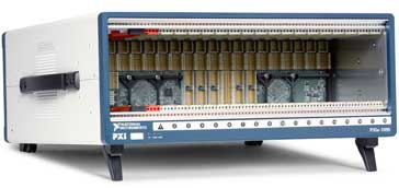
The PXI chassis provides the means by which the whole PXI test system is able to be held together. It provides the services which the individual cards require for the operation. It also provides everything from the mechanical card holders to the power supply and the air cooling required in such a densely packed volume.
The chassis is standardised so that PXI cards and instruments will not only be able to mechanically fit, but electrically operate to their potential within the chassis.
In order to be able to operate correctly, both cards or test instruments and the PXI chassis must conform to the standard. There are a number of salient features within the specification that enable the cards and the chassis to operate together.
PXI chassis environmental requirements
The PXI specifications states that any chassis that are manufactured should be well suited to harsh environments. Although they are not expected to meet the same requirements as military grade equipment, they should nevertheless be able to operate within many industrial environments. For example it may be necessary to operate a PXI chassis in a factory environment for data acquisition where temperatures may vary beyond those seen in a laboratory or where there is some degree of dirty. Certain levels of vibration may also be seen.
To meet these requirements the PXI chassis is based around the Eurocard packaging system used by compactPCI. As part of the system, high performance IEC connectors are used to ensure reliability over long periods of time.
To ensure that the chassis and its associated modules can operate over a sufficiently wide temperature range, the PXI specification includes specific cooling and environmental requirements. These ensure it is able to operate within a variety of industrial environments.
PXI chassis connector system
The connector system used is crucial to its operation. Connectors can be a considerable source of problems, especially when systems are used within non-laboratory environments. Intermittent contacts caused from poor connectors can be particularly time-consuming to fault find. Accordingly a high reliability connector solution was chosen.
Also to maintain compatibility, PXI uses the same pin-in-socket connector system that is found in the CompactPCI racks and systems.
The connectors used in the PXI chassis are defined by the International Electrotechnical Commission, IEC-1076 and offer a high level of performance under all conditions. The connectors pins are on a 2 mm pitch and are also impedance matched so that they provide a high level of performance within the chassis and are able to provide PXI systems more slots on a single bus segment than traditional desktop PCs systems.
Basic PXI chassis parameters
The chassis system is based around the Eurocard packaging system. This provides a number of advantages including a system that is already established. Furthermore the connectors that are used are the IEC-1076 style. The pins are on a 2 mm pitch giving a very dense connection system. In addition to this they are impedance matched to provide the required performance at high frequencies.
The PXI system supports the two sizes, namely 3U and 6U with the details outlined in the table below:
| PXI card sizes | ||
|---|---|---|
| Measurements in mm | Measurements in inches | |
| 3U | 100 by 160 | 3.94 by 6.3 |
| 6U | 233.35 by 160 | 9.19 by 6.3 |
The 3U standard has two interface connectors. One carries the signals required for the 32-bit PCI local bus and the other carries the signals for 64-bit PCI transfers and the signals for implementing various electrical features of the system. The 6U form factor defines modules that may carry up to two additional connectors for future expansion of the PXI specification. The larger card size also allows for a additional circuitry that may be required for some instruments.
In general the 3U PXI chassis and modules are more widely used. However the 3U modules can be fitted into a 6U chassis using a simple adaptor.
PXI chassis widths
PXI chassis come in a number of different sizes and the correct chassis size or type can be chosen for a given application. There is no need to buy a large chassis at extra cost if only a small number of cards are to be used.
Generally there are two sizes of chasses - a full 19 inch rack compatible size and a half rack width.
The full rack width chassis typically has 18 slots, whilst the half sized chassis has 8 slots.
PXI chassis slots functions
Each PXI chassis has a number of slots. As mentioned above the chassis have either eight or eighteen slots. Not all the slots can be used for all cards. There are some positions reserved for particular applications.
- Slot 1: Slot 1 in the PXI chassis is reserved for the controller - this is the only position in which the controller will operate. Normally this is 4 units wide to allow for all the space required for embedded controllers, although some controllers could be smaller. Cards that link out to computers to provide the control are often only one module width and therefore in these circumstances blanking plates may be required to cover the empty space.
- Peripheral slots: These are slots that can be used for the test instruments, etc. There may be some restrictions on the types of module that can be used in terms of PXI, PXIe, etc, but these are indicated by the glyphs on the chassis as described below.
- Timing slot: On larger chassis a timing slot may be indicated. This can be used for normal peripheral modules, but it is also the one to be used if any timing or synchronising modules are to be used. This slot is on the bridge between the two sides of the chassis and it provides the shortest delay between all the modules in the rack.
As a further note, if large amounts of peer to peer streaming is required, then it is best to place the two modules that will be streaming the data on the same side of the backplane bridge, i.e. on the same side of the timing slot.
PXI chassis glyphs
In order to identify the different types of modules that can be accommodated within a PXI chassis, small identification glyphs are used with each slot to highlight what it can accommodate.

The numbers in the glyphs normally refer to the slot number, but in this instance the explanations are linked to the glyph numbers:
- 1 PXI Express system slot
- 2 PXI-1 peripheral slot, i.e. the basic PXI before PXIe was introduced.
- 3 PXI Express hybrid slot - i.e. it will accommodate both PXIe, and the basic PXI
- 4 PXI Express only peripheral slot
- 5 PXI Express system timing slot
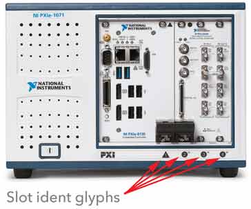
It can be seen how the PXI chassis identification glyphs are shown and how they indicate the capabilities of each slot.
 Written by Ian Poole .
Experienced electronics engineer and author.
More Test Topics:
Data network analyzer
Digital Multimeter
Frequency counter
Oscilloscope
Signal generators
Spectrum analyzer
LCR meter
Dip meter, GDO
Logic analyzer
RF power meter
RF signal generator
Logic probe
PAT testing & testers
Time domain reflectometer
Vector network analyzer
PXI
GPIB
Boundary scan / JTAG
Data acquisition
Return to Test menu . . .


