
Antenna RF Diplexer
Antenna diplexer or RF diplexer splitter / combiner used for combining and splitting RF feeders so they can be used by multiple transmitters or receivers and possibly on different frequencies.
Home » Antennas & Propagation » this page
Antenna Diplexer Includes:
Diplexer basics
An antenna diplexer or RF diplexer is a unit or module that enables two antenna feeds to be combined and carried down one feeder. Conversely, it can act as a splitter to enable the signal from one feeder to be connected to two receivers or antennas.
Antenna diplexers are available in a variety of formats and within a range of different powers, so that they can meet the needs of a variety of different applications needs.
Antenna diplexer applications
Antenna diplexers find many uses. Diplexers can be used in a variety of different ways, so there is no method or way in which they must be used. Accordingly they can be used for a number of different applications.
- Enabling multiple transmitters to use a single antenna: Broadcast stations often use multiple frequencies, possibly for different programmes / station names. In view of the size and cost of the antennas they may have a single vertical antenna and they may want to combine the signals from several transmitters to feed into the antenna. As they are on different frequencies, it is possible to use a diplexer to combine the signals and use a single feed.
- Enabling a multiband transmitter to use different antennas according to frequency : Some transmitters like some ham radio transmitters can cover very wide ranges of bands - for ham radio transmitters there is a growing trend towards transmitters covering HF and VHF bands. They may even extend into the UHF region. Often one antenna system may be used for HF operation, and another for V/UHF operation. If there is a single transmitter output, a diplexer can be used to route HF signs to the HF antenna, and V/UHF signals to the V/UHF antenna.
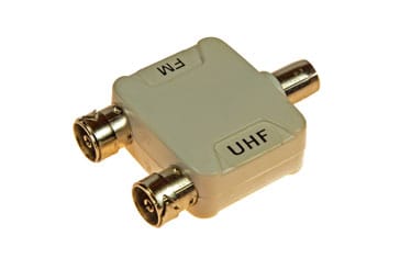
- Allowing single feeder to be used for multiple feeds, e.g. TV & radio: within a domestic scenario, it is often useful to have an external VHF FM or digital radio antenna along with a television antenna using single feeder. The signals from he antennas can be combined at the antenna end using diplexer, and a second diplexer at the point of use to route the signals to the radio and television. This can work well because television signals typically use frequencies above 300 MHz, often 400MHz and more, whereas VHF FM radio is between 87.5 and 108MHz, of within the VHF band is digital radio is used.
Diplexers & duplexers
the terms diplexer and duplexer tend to be used interchangeably in many instances, although diplexers and duplexers are different, even if the definitions can be rather fluid in occasions.
- Diplexer definition: A diplexer is a device that enables different devices to share a common feeder or resource. It typically consists of filters (Low Pass, High Pass or Band Pass) at different frequencies connected to to allow the sharing. For a diplexer, the signals need to be vat different frequencies to allow them the different outputs / inputs to be sufficiently separated using the filters.
- Duplexer definition: A duplexer is a device that allows duplex operation a device to allow transmitters and receivers on slightly different frequencies on the same band to use the same antenna. It isolates the transmitter from the receiver, giving sufficient isolation for them to operate at the same time. A circulator is an ideal example of a duplexer.
It should also be noted that a diplexer is different to the traditional form of power divider or splitter. Even though the feed line is combined or split, any power that may be split is not divided between the two outputs as they are isolated from each other, and the output selection is frequency dependent. The signal loss, from input to the relevant output should be as low as possible.
Basic antenna diplexer concepts
There are a number of ways of implementing RF diplexers. They all involve the use of filters. In this way the paths for the different transmitters and receivers can be separated according to the frequency they use. The simplest way to implement a diplexer is to use a low pass and a high pass filter although band-pass filters may be used. In this way the diplexer routes all signals at frequencies below the cut-off frequency of the low pass filter to one port, and all signals above the cut-off frequency of the high pass filter to the other port. Also here is no path from between the two remote connections of the filters. All signals that can pass through the low pass filter in the diplexer will not be able to pass through the high pass filter and vice versa.
A further feature of an RF diplexer is than it enables the impedance seen by the receiver or transmitter to remain constant despite the load connected to the other port. If the filters were not present and the three ports wired in parallel, neither the antenna nor the two transmitter / receiver ports would see the correct impedance.
RF diplexer filter requirements
When designing an antenna diplexer a number of parameters must be considered. One is the degree of isolation required between the ports labelled for the high and low frequency transmitter / receiver. If the diplexer is to be used purely for receiving, then the requirement for high levels of isolation is not so high. Even comparatively simple filters give enough isolation to ensure each receiver sees the right impedance and the signals are routed to the correct input without any noticeable loss. Even levels of isolation of 10 dB would be adequate for many installations. For diplexers that are used to split and combine television and VHF FM radio along a single line, te levels of isolation are likely to be very low.
The next case is when the diplexer is to be used for transmitting only. It will be necessary to ensure that the levels of power being transferred back into a second transmitter are small. Power being fed into the output of a transmitter in this way could give rise to intermodulation products that may be radiated and cause interference. It is also important to ensure that the transmitters see the correct impedance, and that the presence of the second transmitter does not affect the impedance seen by the first. Typically levels of isolation between the transmitter ports of 60 - 90 dB may be required.
The final case is where one of the ports is used for transmitting, and the other for receiving simultaneously. In this instance very high levels of isolation are required to ensure that the minimum level of the transmitter power reaches the receiver. If high levels of the transmitter signal reach the receiver, then it will be desensitised preventing proper reception of the required signals. Levels of isolation in excess of 100 dB are normally required for these applications.
Band pass filters
Under some circumstances band pass filters may be used. These may be used where comparatively narrow bandwidth is required for either or both of the transmitter / receiver ports. Sometimes a very high Q resonant circuit may be used. By using this approach high degrees of rejection can be achieved. Often repeater stations which receive on one channel and transmit on another simultaneously use diplexers that utilise this approach.
Although antenna diplexers are mainly used in specialised applications, allowing a single Rf antenna to be used by more than one transmitter or receiver, they are nevertheless a crucial element of many installations. For example cellular technology would be significantly different if they could not be used and the cellular RF antennas for base stations would be considerably more complicated. Similarly antenna diplexers are used in many broadcast applications allowing a single large RF antenna to be used by more than one transmitter.
 Written by Ian Poole .
Experienced electronics engineer and author.
More Antenna & Propagation Topics:
EM waves
Radio propagation
Ionospheric propagation
Ground wave
Meteor scatter
Tropospheric propagation
Antenna basics
Cubical quad
Dipole
Discone
Ferrite rod
Log periodic antenna
Parabolic reflector antenna
Phased array antennas
Vertical antennas
Yagi
Antenna grounding
Installation guidelines
TV antennas
Coax cable
Waveguide
VSWR
Antenna baluns
MIMO
Return to Antennas & Propagation menu . . .


