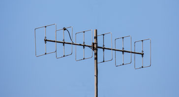
Cubical Quad Antenna
The cubical quad antenna provides advantages over traditional aerials. Find out what the cubical quad antenna is, how it works, operation, design, etc.
Home » Antennas & Propagation » this page
Cubical quad antenna includes:
Cubical quad antenna basics
2 metre cubical quad design
The Cubical Quad or Quad antenna has traditionally not been as widely used as its more popular cousin the Yagi. However the cubical quad beam antenna is able to provide some advantages in a number of circumstances.
Since its first introduction, the quad antenna has found uses in a number of areas. It has been used for some television antennas, but it has also seen a lot of use within amateur radio applications for use at HF and VHF / UHF.
Although the cubical quad antenna is not nearly as widely used as the Yagi, it still has advantages and can be used to good effect in many instances.
Origins of the cubical quad antenna
The cubical quad antenna has its roots in the early 1940s. It was developed because of some specific needs at the HCJB Christian radio station in Ecuador.
Their high power transmitting installation used a 10-kilowatt transmitter and a four element Yagi. There were issues with the antenna where the ends melted as a result of the intense electrical breakdown resulting from a combination of high electrical potentials at high altitude.
An engineer named Clarence Moore who also held an amateur radio licence with the callsign W9LZX, led a team to devise a solution.
During a 1942 retreat, Moore and his colleagues conceptualized a loop antenna with no ends, dubbed the cubical quad, to eliminate corona discharge problems prevalent at high altitudes.
The new antenna design featured a square loop driven element and a reflector loop, tuned slightly lower, which successfully handled the power without issues. There were no open ends where the discharges wouold occur.
The success of the new antenna at HCJB sparked interest within the amateur radio community. Famous author of many amateur radio magazine articles and books, William Orr, callsign W6SII, further popularized it through extensive research and publications, refining its design.
Quad antenna basics
The basic quad element can be seen to be derived from two dipole elements stacked one above the other and fed in phase. This arrangement in itself gives gain because of the phasing effect between the two dipoles.
The next stage in the evolution is to retain the two separate dipoles but bend the ends together. It is found that the voltages at the ends of the antennas are in phase with one another.
As a result it is possible to connect these ends together and remove one of the feeders to create the basic quad element. As such the loop forming the element is a full wavelength with each side being a quarter of a wavelength.

Often the cubical quad is constructed by having an ‘X’ frame made from insulating material, even wood, and then using this to support the wire or tube that forms the conducting radiating element.
In some instances where antennas are small enough and the tubing is sufficiently robust, it is possible to rely on the strength of the tubing alone for the mechanical strength. This is normally only achieved at VHF or better still UHF.

This format gives a maximum radiation perpendicular to the plane of the square of the loop, and in this format the radiation is horizontally polarised.
Although the format of the horizontal square for the cubical quad is the more obvious format and the more common, it is also possible to turn the square format through 45°.
When this format is used it should be remembered that the width of the antenna is equal to the diagonal of the square, whereas when the horizontal square is used, then the width is equal to only bottom of the square.

Sometimes the diamond style construction can provide a attractive option for construction. One point to note when using this configuration is that the two side mounting points labelled ‘a’ for the wires are at the voltage maximum points. Points marked ‘b’ form the current maximum points. For higher power levels it may be necessary to utilise some form of proper insulator at the voltage maximum points.
Both the diamond and familiar horizontal square version of the cubical quad antenna produce a horizontally polarised signal. To generate a vertically polarised signal the whole antenna should be rotated through ninety degrees so that the feed point is at the central point of the vertical section of the "square" version or in one of the "side" corners of the "diamond" version.
Quad beam antenna: the reflector and director
A reflector can be added behind the driven element to make a cubical quad beam antenna. To give the right phasing of the currents in the elements of the beam antenna for it to reflect, it should be made inductive, and this can be accomplished by tuning it below resonance. This can be achieved in a number of ways.
The first is to make the reflector slightly longer than the electrical full wavelength. Typically it is made between 3 and 5% longer. The extended length is not particularly critical with little change in performance between about 3 - 5% longer in length.

Directors can also be made in a similar fashion. They need to be capacitive to have the right current phasing and this can be achieved by tuning the element above resonance and making the element slightly shorter than the electrical full wavelength. Again the first director can be about 3 - 5% shorter. Subsequent directors should slowly decrease in length as further directors are added.
An alternative method of lengthening and shortening the parasitic elements is to insert a stub. This has the advantage that the element can be made exactly the same size as the driven element, and this may have some mechanical advantages for the quad beam antenna.
The reflector requires a short circuit stub - this can be made of a couple of stiff wires connected to an equivalent pont tot he feed point on the driven element. The position of the short can be made to be adjustable, although the position tends not to make a huge performance difference.
Similarly directors can also use a stub to give the required characteristics, but in this case an open circuit stub is used.
It must be said that some do not like using the stub approach because of the difficulty of tuning the antenna, but it worked satisfactorily for my installation, although detailed measurements were not made.
Element spacing
In the same way that the element spacing played a large part in the design of the Yagi beam antenna, the same is found for the quad. In general a spacing of around 0.15 to 0.2 of a wavelength is used. This conveniently gives a feed impedance of around 50Ω.
If a two element quad beam antenna has a spacing of just over a quarter of a wavelength then the feed impedance rises to around 75Ω. This is convenient for designs used for VHF FM broadcast reception. If the spacing is reduced below about 0.15 wavelengths then the impedance falls. If this is done then some form of impedance transformation would be required to enable the antenna to be fed by standard coax.
The spacing also has some effect on the gain. However as in the case of the Yagi the effect is fairly small and the impedance matching is the major requirement whilst adjusting the spacing for the cubical quad beam antenna.
Gain and directivity
As with many antennas the level of gain for the cubical quad beam antenna is an important factor of its overall performance.
The basic cubical quad driven element on its own has a gain of about 2dB over a dipole because it is essentially a pair of stacked dipoles. It is generally about 2dB.
The addition of a reflector adds about 5dB gain and a director about an additional 2dB. Further directors average out at giving very approximately one dB each. This means that a quad having the same number of elements as a Yagi will have about 2dB further gain. In fact the comparison should be made between antennas having a similar length and designed to have optimum element spacing.
The front to back ratio is also quite reasonable. A typical antenna might produce a figure of 10dB, and the adjsutment of the antenna is by no means critical - the reflector just needs to couple well with the driven element.
It is found that adding a large number of quad directors produces diminishing returns, and the limit is generally accepted to be about four or five. If much greater gain and directivity is required then it becomes more viable to use the Yagi approach or the hybrid quagi design which typically uses the driven element and reflector from a quad beam antenna and the directors in the form of those used by a Yagi..
When deciding upon a high gain cubical quad beam antenna design it is worth remembering that quad antennas are more prone to wind damage, and as a result they have tended to fall out of favour. Any that are built should be sturdily constructed if they are to be used externally.
Current & voltage distribution
From the development of the basic quad element it is fairly easy to deduce where the current and voltage maxima will be. As the current maximum is at the feed point the same is also true for the quad. There is also another current maximum on the opposite side of the loop to the feed point i.e. where the second feed point was.The voltage maxima appear at points a quarter of a wavelength away from the feed point i.e. where the two ends of the dipole would have been. In view of the position of the voltage points it is often advisable not to position any fixings at these points.
Advantages & disadvantages
Since the introduction cubical quad beam antenna there has always been considerable debate about its advantages compared to the more familiar Yagi.
As with any antenna there are always advantages and disadvantages that need to be balanced to see what is the most attractive option for any given situation.
Cubical quad advantages:
- Gain: The cubical quad beam antenna offers about 2 dB over a Yagi of a similar length. This means that the quad compares to a pair of stacked Yagis as there is always some loss in the feed arrangements for stacking the two antennas.
- Lower noise: It has been demonstrated that a quad tends to provide lower noise reception compared to a Yagi.
- Low angle radiation: The fact that the quad antenna is effectively a pair of stacked dipoles, it offers a lower angle of radiation than that provided by a single Yagi. It compares to a pair of stacked Yagis.
- Effects of close objects: The quad antenna is less affected by nearby objects, giving it an edge over the Yagi in many installations, especially those that are inside, possibly in the loft or attic.
- Internally stackable: One advantage of the cubical quad antenna is that it is possible to internally stack separate quad antennas for multiple bands under some circumstances. This option is used mainly on the HF bands.
- Reduced turning circle: This will be noticed most for a two element beam. As the elements do not extend out as far as those of an equivalent Yagi, the turning circule for a two element beam will be half that of an equivalent Yagi.
- Bandwidth: The quad antenna offers a wider bandwidth than many other antennas such as the popular Yagi because of its inherently low Q. This means that it can cover a complete band and does not need to be optimised for the top middle or bottom ends as many other antennas do.
Cubical quad disadvantages:
- Construction: The construction of the quad antenna is not as straightforward as a simple Yagi. It requires a more complicated form of construction.
- Cost: The more complicated construction can sometimes result in higher costs for a quad than for a Yagi. This has meant that for commercial VHF / UHF operation it is rarely used. That said for amateur radio HF operation, it enabled home made construction with wire and other items available from many hardware stores to provide some cost effective installations.
- Robustness: The quad antenna is larger than its equivalent Yagi and the ‘spider’ arrangement used on many HF bands is often not as robust as a Yagi.
The characteristics of the cubical quad mean that it is used in a number of situations. It was popular some years back as a UHF television antenna, but now it is less widely seen. It is still used for amateur radio operations both at HF and VHF / UHF where its features bring several advantages.
 Written by Ian Poole .
Experienced electronics engineer and author.
More Antenna & Propagation Topics:
EM waves
Radio propagation
Ionospheric propagation
Ground wave
Meteor scatter
Tropospheric propagation
Antenna basics
Cubical quad
Dipole
Discone
Ferrite rod
Log periodic antenna
Parabolic reflector antenna
Phased array antennas
Vertical antennas
Yagi
Antenna grounding
Installation guidelines
TV antennas
Coax cable
Waveguide
VSWR
Antenna baluns
MIMO
Return to Antennas & Propagation menu . . .