
Antenna Ground Plane: theory & design
Using an antenna ground plane can enable a simulated ground to be made and allow the antenna to be mounted above ground.
Home » Antennas & Propagation » this page
Antenna Grounding Includes:
How to ground an antenna
Antenna RF ground
Antenna ground plane
Ground mounted antennas are often very easy and convenient to use. They are often convenient and easy to use.
However when it is not possible to ground mount an antenna because of ground conditions or it is necessary to elevate the antenna, another solution is to use a ground plane.
What is an antenna ground plane?
As the name indicates the antenna ground plane acts as a simulated ground. It is found that for a monopole antenna like a quarter wavelength vertical, the ground acts as a plane to reflect the radio waves so that an image of the top half of the antenna is seen in the Earth. It is possible to simulate this function by replacing the real earth with a conducting plane. To function as an antenna ground plane, the conducting surface must extend for least a quarter wavelength from the base of the antenna.

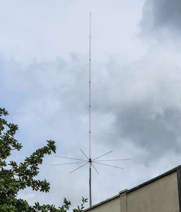
In reality it is not necessary to have a full circular conducting plate for a ground plane. This would be difficult to manage in terms cost and also the wind resistance. In stead it is normally sufficient to have a ground plane consisting of a number of quarter wavelength radials. Often four conducting radials are used and these often provide a sufficient simulation of the complete circular ground plane.

It is not always necessary to have a minimum of four radials – often even two will suffice. It is also possible to shorten them with marginal impact on the performance, especially if they are loaded to keep their electrical length.
The feed impedance of a quarter wavelength vertical fed against a ground plane is 37&Omega: against that of a dipole which is 73Ω. This can be an issue if the antenna needs to be fed with standard 50Ω coaxial feeder. To overcome this, the ground plane conductors can be bent downwards from the horizontal raise the feed impedance. A 50Ω match will be achieved when the angle between the ground plane rods and the horizontal is 42 degrees.
If the radials are dropped even further, the impedance rises even more and in the limit condition, the radials all run in the same axis as the main radiating element to form a vertical dipole for which the radiation resistance / feed impedance is &73Ω
Physical realisation of ground plane conductors
The standard ways in which the ground plane conductors are made varies with the operating frequency of the antenna and hence the length of the conductors.
At HF, the conductors tend to be ordinary wires attached to the ground point on the antenna. These are run to convenient points where they can be anchored. Typically an insulator is required at the end of the conductor.
At VHF and above, the conductors are much shorter and they tend to be made from rods – normally the same material as the vertical element itself.
 Written by Ian Poole .
Experienced electronics engineer and author.
More Antenna & Propagation Topics:
EM waves
Radio propagation
Ionospheric propagation
Ground wave
Meteor scatter
Tropospheric propagation
Antenna basics
Cubical quad
Dipole
Discone
Ferrite rod
Log periodic antenna
Parabolic reflector antenna
Phased array antennas
Vertical antennas
Yagi
Antenna grounding
Installation guidelines
TV antennas
Coax cable
Waveguide
VSWR
Antenna baluns
MIMO
Return to Antennas & Propagation menu . . .


