Transformer Concepts, Formulas & Calculations
Transformers are widely used in electronic circuit designs and their operation depends upon a number of basic concepts along with a number of formulas that can be used to understand their operation.
Inductance and Transformer Tutorial Includes:
Inductance
Symbols
Lenz's law
Self inductance
Inductive reactance calculations
Inductive reactance theory
Inductance of wire & coils
Mutual inductance
Transformers
Transformers are electronic components that widely used in all branches of electrical and electronic technology.
They consist of two or more windings that are resistively isolated, but are magnetically coupled so that varying signals on one winding are linked to another winding.
Transformers are well known uses is in power applications where they are used to transform the operating voltage from one value to another as well as resistively isolating two circuits.
They also serve to isolate the circuit at the output from a direct connection to the primary circuit. In this way they transfer power from one circuit to another with no direct connection.
However, transformers can be used in many other areas of electronic circuit design where they are used for audio signals, radio frequency, RF design as well as many other areas.
Transformers are a very important form of electronic component, and although their cost is high because in general each one needs to be wound separately, they are still used in a large quantities and in a huge number of electronic circuits designs.
What is a transformer
A transformer is a form of electronic component that uses the mutual inductance between two coils to link one circuit to another.

This one is an air cored transformer
Note on transformer electronic components:
Transformers are available in many forms for different uses in various electronic circuit designs. Some provide voltage transformation for line or mains power, others may be used for audio or RF applications.
Read more about Transformers
Accordingly, a basic transformer consists of two windings. These are known as the primary and the secondary. In essence power enters on the primary, and leaves on the secondary. Some transformers have more windings but the basis of operation is still the same.
There are two main effects that are used in a transformer and both relate to current and magnetic fields. In the first it is found that a current flowing in a wire sets up a magnetic field around it.
The magnitude of this field is proportional to the current flowing in the wire. It is also found that if the wire is wound into a coil then the magnetic field is increased.
If this electrically generated magnetic field is placed in an existing field and as a result a force is exerted on the wire carrying the current in the same way that two fixed magnets placed close to one another will either attract or repel one another. It is this phenomenon that is used in electric motors, meters, and a number of other electric units.
The second effect is that it is found that if a magnetic field around a conductor changes then an electric current will be induced in the conductor. One example of this can occur if a magnet is moved close to a wire or a coil. Under these circumstances an electromotive force is induced, but only when the magnet is moving.
The combination of the two effects occurs when two wires, or two coils are placed together. When a current changes its magnitude in the first, this will result in a change in the magnetic flux and this in turn will result in a current being induced in the second.
This is the basic concept behind a transformer, and it can be seen that it will only operate when a changing or alternating current is passing through the input or primary circuit.
Transformer turns ratio
For a current to flow an EMF (electro-motive force) must be present. The induced electromotive force is dependent upon the ratio of turns in the transformer.
It is found that if more turns are present in the primary than the secondary, the voltage at the input will be greater than the output and vice versa. In fact the voltage can easily be calculated from a knowledge of the turns ratio:
Where:
Ep is the primary EMF
Es is the secondary EMF
Np is the number of turns on the primary
Ns is the number of turns on the secondary
If the turns ratio Ns/Np is greater than one then the transformer will give out a higher voltage at the output than the input and it is said to be a step up transformer. Similarly one with a turns ratio less than one is a step down transformer.
Voltage and current ratios across the transformer
There are a number of other parameters of importance that can be calculated very easily. The first is the ratio of input and output currents and voltages.
The principle of energy conservation states that energy is neither created nor destroyed. This means that apart from any losses within the transformer which will be minimised in the design, the input power must equal the output power.
Accordingly, the input voltage times the current equals that of the output:
Where:
Vp is the primary input voltage
Vs is the secondary or output voltage
Ip is the current in the primary winding
Is is the current in the secondary winding
For example take the case of a mains transformer that gives out 25 volts at one amp. With an input voltage of 250 volts this means that the input current is only a tenth of an amp.
Obviously some losses occur, but the efficiency of most transformers is very high and therefore these losses are normally ignored. Normally what happens is that the secondary voltage drops when the transformer is placed under load.
Transformer impedance transformation
For some transformers the number of turns on the primary will be the same as that on the secondary, and the current and voltage at the input will be the same as that at the output.
However where the turns ratio is not 1:1, the voltage and current ratio will be different at the input and the output. From the simple relationship shown above it will be seen that the ratio of voltage to current changes between the input and the output if the turns ratio is not 1:1.
For example a transformer with a turns ratio of 2:1 may have a 20 volt input with a current of 1 amp, whereas at the output the voltage will be 10 volts at 2 amps.
As the ratio of voltage and current determines the impedance, it can be seen that the transformer can be used to change the impedance between the input and the output. In fact the impedance varies as the square of the turns ratio as seen by:
Where:
Zp is the impedance of the primary circuit
Zs is the impedance of the secondary circuit
Np is the number of turns in the primary winding
Ns is the number of turns in the secondary winding
Transformer cores
The examples described so far have all been for air cored transformers. One of the issues with these air-cored transformers is that the magnetic flux between the two coils is not well linked. The flux from the primary will not be channelled so that the maximum amount of the flux actually links with the secondary circuit and this leads to significant levels of in-efficiency.
In order to get better flux linkage between the primary and secondary circuits of a transformer, a ferro-magnetic core is used.
The primary and secondary windings are wound around the core and it then contains the flux from the windings and links the two, or more windings far more effectively.
A variety of core materials and shapes can be used dependent upon the electronic circuit design, the requirements and the frequencies in use.
Some transformers may use layered iron cores whereas others may use ferrite, etc. The actual shape and material depend upon what is needed.
Transformer applications & circuits
Transformers are used in very many areas of electronic circuit design and radio frequency, RF design.
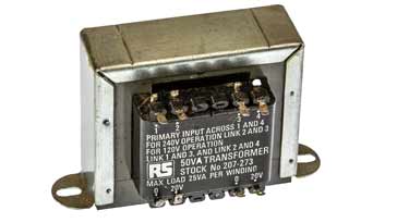
One of their main uses is within mains power supplies. Here the transformer is used to change the incoming powerline or mains voltage (around 240 V in many countries, and 110V in many others) to the required voltage to supply the equipment.
With most of today's equipment using semiconductor technology, the voltages that are required are much lower than the incoming power line voltage.
In addition to this the transformer isolates the supply on the secondary from the mains, and thereby making the secondary supply much safer. If the supply were taken directly from the mains supply then there would be a much greater risk of electric shock.
The two windings of a power transformer are well insulated from one another. This prevents any likelihood of the secondary winding from becoming live.
Transformers were also used for a variety of other functions within electronic circuit designs.
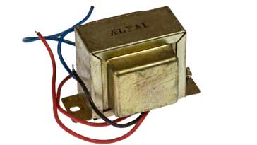
One application was as an audio output transformer. Here, the high impedance of the output stage was converted down to the more usual low impedance required for a loudspeaker. This approach was used within some early transistor portable radios as well as within radios using valves / tubes.
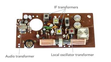
Another use for transformers, again within radios was as IF transformers. These not only provided impedance matching between stages, but also they were tuned to give the selectivity.
In addition to these examples, transformers are used in very many other electronic circuit designs, RF designs and other areas.
Transformers are an essential element of many circuits, providing the required voltage and impedance transformations as well as isolating the two sides of the transformer in terms of the the DC voltage.
Transformer summary sheet
It's often useful to have a summary about transformers with some of the basic circuit symbols and equations that are widely used.
Here at Electronics Notes, I've put together a quick summary sheet to give some of the basics of the transformer and some of the basic and more widely sued equations.
The equations assume a lossless transformer, and in most cases this is a valid assumption because generally the losses are small.
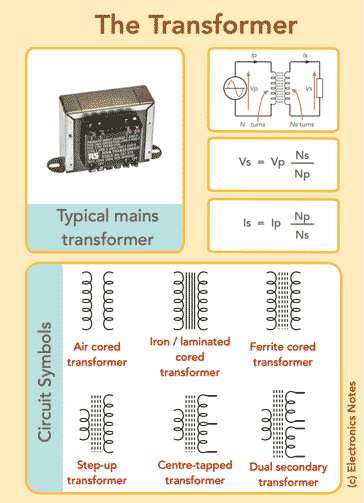
Click on image for larger version
The transformer is an invaluable component in today's electronics scene. Despite the fact that integrated circuits and other semiconductor devices seem to be used in ever increasing quantities, there is no substitute for the transformer. The fact that it is able to isolate and transfer power from one circuit to another whilst changing the impedance, ensure that it is uniquely placed as a tool for electronics designers.
 Written by Ian Poole .
Experienced electronics engineer and author.
More Basic Electronics Concepts & Tutorials:
Voltage
Current
Power
Resistance
Capacitance
Inductance
Transformers
Decibel, dB
Kirchoff's Laws
Q, quality factor
RF noise
Waveforms
Return to Basic Electronics Concepts menu . . .