
Transformer Types & Applications
There are many different types of transformer that are essential electronic components within a variety of electronic circuit designs providing isolation, voltage transformation, impedance transformation, etc, each one having its own characteristics and function.
Home » Electronic components » this page
Transformers Includes:
Transformers, types, applications
Pulse transformers
Autotransformers & Variacs
See also:
Inductor types
Inductor specifications
Transformers are electronic components that are used in a wide number of areas of electronic circuit design from low frequencies right up to radio frequencies.
Transformers are used in electronic circuit designs for a variety of purposes including resistively isolating input and output circuits as well as impedance transformation and for providing frequency selectivity.
Accordingly there are very many different types of transformer that can be made, with a variety of sizes, form factors and performance parameters.
When looking at transformers it is essential to understand not only how they work and the basic theory of their operation, but also the function they are required to provide within the circuit.
Basic transformer theory
A basic transformer typically consists of two coils that are coupled by an induced magnetic field that interlinks them both. Essentially a transformer is made by placing two coils of wire close enough to each other - in theory two wires can be used, but the magnetic field between them both is so small that the effects can often be ignored.
Normally the coils are made into an assembly as a single electronic component and a ferromagnetic core is often used within this to increase the linkage or mutual inductance between the colis
Using the standard formulas or equations for transformers, it is possible to calculate figures including the output voltage, impedance transformation ratio, turns ratio required for a given transformation, etc.
Note on Transformer Concepts:
Transformers are widely used in electronic circuit design and the basic concepts and formulas for them enable the performance and parameters to be calculated and understood.
Read more about Transformer Concepts
Transformer circuit symbol
there are very many different types of transformer that are available and as a result many of these different types need to have different circuit symbols.
Although they all have the same basic elements of the transformer circuit symbol, they differ in terms of the core used, any taps that may be present and also an indication of the different turns ratios.
| Transformer Circuit Symbols |
|
|---|---|
| Air cored transformer |  |
| Air cored transformer with unequal turns ratio side with fewer turns can be either side of transformer symbol according to the turns ratio. |
 |
| Air cored transformer with tap taped connections are used to give a different turns ratio for a particular output, or input and often provide impedance or voltage transformation |
 |
| Ferrite cored transformer |  |
| Iron or laminated cored transformer |  |
Although these are the main types of transformer circuit symbol that will be seen, other types may be used within circuit diagrams for electronic circuit designs to provide different functions. One common example is where multiple windings may be used, or where electrostatic screens are placed between the windings, etc.
Transformer uses
Transformers are used in many ways in a variety of different electronic circuit designs. Although the basic theory is the same, these electronic components can be sued to provide a number of different functions in a circuit.
One of the most common applications for these electronic components are widely used in power circuits, but they are also used within RF designs and also in a variety of isolation applications.
The actual parameters for transformers used in these different applications varies considerably and as a result their construction, their sizes and their properties are very different.
As a result it is useful to see where transformers can be used in electronic circuit designs and the different parameters that are needed in each of them.
• Power line / Mains isolation:
One of the key functions of transformers in many circuits is to provide resistive or galvanic isolation between the input and output circuits.
One of the most common areas where the isolation of transformers is put to good use is within power supply units where the input transformer is used to enable the equipment supplies to be isolated from the powerline or mains input.
By having a resistive isolation from the incoming power line, the output voltage and power from the power supply unit is much safer. If the power supply did not have the isolation in place, there could be a danger of the output from the power supply unit becoming live, which in turn could make any unit being powered become live.
This is an important function of a transformer and one which will have saved many lives over the years.
• Pulse transformers:
The resistive or galvanic isolation provided by transformers is also used in many other areas and electronic circuit designs.
They can be used as pulse transformers - a form of transformer optimised for pulses. Pulse transformers are a broad family of transformers that are designed and optimised for the transfer of a digital control signal from a control circuit to a load.
Pulse transformers provide galvanic isolation to a circuit, whilst still allowing the fast control signals to be transmitted. A key requirements is that the pulse signal shape is not distorted.
The signal carried by a pulse transformer is typically a rectangular wave of a few volts with a frequency above 100KHz. The signal carried by a pulse transformer differs from normal transformers because it is rectangular and not a sinusoidal.
• Transformers for giving isolation for testing:
There are many situations where galvanic or resistive isolation is needed in a situation where a test signal is required. It might be that a signal on a high voltage line might require testing. If a transformer were not included then the voltages present on the test equipment could present a significant safety hazard.
By placing a transformer in the line where the signal needs to be sampled, isolation can be achieved and the safety issue can be overcome.
Although the obvious area where these transformers are used can be within high voltage testing situations, they are also widely used in medical equipment to ensure that any risk to patients who are often connected to medical instruments is completely removed. Even relatively low levels of leakage could be fatal in some circumstances.
• Voltage transformation:
Another important aspect of these electronic components is to act as a voltage transformer. Given a fixed input voltage such as a power line or mains input, it is possible to wind the transformer so that a different output voltage is obtained.
In fact this is another of the purposes of using a transformer - in fact the name even implies that it transforms the voltage.
Using a transformer it is possible to transform one voltage to another with little loss of power - transformers are normally very efficient.
A typical transformer may be used to convert the incoming power line or mains input of 110V or 240V down to a level more suitable for powering the equipment - often10, 15, or whatever voltage is needed.
The output from the transformer is typically fed into a rectifier to convert the power from AC to DC and then it will be smoothed.

After the smoothing, the voltage may then be applied to a linear regulator to provide the required output voltage with little ripple and noise.
• Impedance transformation and matching:
By having a different number of turns on the various coils or windings of the transformer, it is possible to change the voltage between the input and output. As the power between input and output is the same (provided the losses can be ignored) then it is found that the voltage to current ratio will change. This means that the impedance at the input and output is changed.
In fact the ratio of voltage and current has changed, means that the impedance must have changed.
It is possible to calculate the impedance transformation from the ratio of the turns as seen in the formula below.
Where:
Zp is the impedance of the primary circuit
Zs is the impedance of the secondary circuit
Np is the number of turns in the primary winding
Ns is the number of turns in the secondary winding
Using transformers to change the impedance finds applications in many circuits. In particular it is used in many elements of RF design where impedance matching is essential.
There are many RF design instances where impedance matching is needed. Impedance matching transformers are widely used in receivers and especially in transmitters where it is imperative to obtain the optimum matching to ensure the RF power is used effectively when transferring from one stage tot he next, and especially for the power output stage.
Impedance matching transformers are also used in RF mixers where it is important to have the right impedance match to ensure the correct operation of the mixer and in particular the required suppression of spurious signals.

Impedance matching transformers are also seen in some older audio amplifiers and radios where the higher impedance of the audio output stage, either valve / tube or sometimes transistor needs to be matched to the low impedance of the loudspeaker.
Also matching transformers may be used where the audio needs to be matched to a 600Ω line circuit.
• Resonant transformers:
There are a number of instances where the transformers are made resonant, typically by adding a capacitor across the winding.
One of the most common areas where this approach could be seen was in older radios where the intermediate frequency transformers were tuned, becoming bandpass filters and providing the main adjacent channel selectivity for the radio.
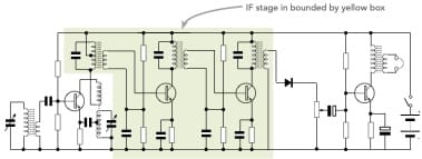
As these filters were simply LC filters, they did not provide sufficient selectivity for most high performance radios which used additional crystal or other filters. However, the tuned IF transformers provided the main selectivity for most broadcast radios prior toth e 1980s or thereabouts.
Transformer cores
The core within a transformer determines many of its properties. Transformers with air cores, i.e. no core apart from the surrounding air have much lower levels of mutual inductance.
Adding a core of a ferromagnetic material not only enhances the inductance of the individual coils or windings, but it also increases the linkage between the two, i.e it increases the mutual inductance as it guides the flux through both coils.
There are many different patterns for cores - this is a topic in its own right. The different transformer core patterns as well as toroidal cores.
There are also very many different materials used for inductor and transformer cores. The type of core used will depend upon the power levels, frequency of operation and various other parameters all defined by the particular electronic circuit design.
Although transformers are not as widely used as they were many years ago as a result of the cost of winding and the change in the way that electronic circuit designs can be configured these days.
Nevertheless, transformers are still used in a host of different areas and they are still a key electronic component for many circuits, equipments and designs.
 Written by Ian Poole .
Experienced electronics engineer and author.
More Electronic Components:
Batteries
Capacitors
Connectors
ADC
DAC
Diodes
FET
Inductors
Memory types
Phototransistor
Quartz crystals
Relays
Resistors
RF connectors
Switches
Surface mount technology
Thyristor
Transformers
Transistor
Unijunction
Valves / Tubes
Return to Components menu . . .


