
Electromechanical Relay
An electromechanical relay is an electrical switch that is typically operated by using electromagnetism to operate a mechanical switching mechanism.
Home » Electronic components » this page
Relay Technology Includes:
Relay basics
Reed relay
Reed relay specs
Relay circuits
Solid state relay
An electrical relay is an electromagnetically operated electrical switch - an electromechanical switch. A relatively small current is used to create a magnetic field in a coil within a magnetic core and this is used to operate a switch that can control a much larger current.
In this way an electromechanical relay or electrical relay can use a small current to switch a much larger current and enable both circuits to be electrically isolated from each other.
Electrical relays come in a variety of different sizes and they can be of a variety of different types using slightly different technologies, although they all use the same basic concept.
Although electromechanical relays may be considered in some respects to use old technology, and solid state relays / solid state switches might be thought to be a more effective means of switching electrical current.
Nevertheless electromechanical relays have some unique properties that make them ideal for many applications, where other types may not be as effective.
That said, solid state switches, solid state relays or electronic switches are widely used and have taken over in many areas where electromechanical relays were previously used as electrical switches.
Relay circuit symbol
When drawing the schematics for electronic circuit designs, it is necessary to have the circuit symbols for the required electronic components. Ideally these symbols should be standardised so that everyone understands exactly what they mean.
Unfortunately, the circuit symbols for electromechanical relays can vary somewhat. The most widely used format shows the relay coil as a box, and the contacts are placed close by as shown below.
The methods for indicating the normally closed and normally open contacts are indicated on the diagram - these are normally critical in most circuits.

Note that on this symbol, both normally open and normally closed contacts are shown. Where one or more sets of contacts is not used, it is often not shown.
Other circuits, especially new that may be a bit older may show the relay coil as an actual coil. Although this does not conform to the latest relay circuit symbol standards, it may nevertheless be seen in some instances and it describes the inside of the relay well.

An older style showing the relay coil.
It is possible for there to be further sets of electrical switch contacts. In the same way that it is possible to have multiple poles on a switch, the same can be done with relays. It is possible to have several sets of switch contacts to change over multiple circuits.

An older style showing the relay coil.
Relay switch basics
A relay is a form of electrical switch that is operated by electromagnet which changes over the switching when current is applied to the coil.
These relays may be operated by switch circuits where the switch cannot take the high current of the electrical relay, or they may be operated by electronic circuits, etc. In either circumstance they provide a very simple and attractive proposition for electrical switching.

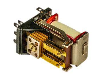
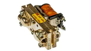
Relays have a number of basic parts that form the relay.
- Frame: A mechanical frame is required to hold the components in place. This frame is normally quite robust so that it can firmly support the additional elements of the electromechanical relay without relative movement.
- Coil: A coil wound round an iron core to increase the magnetic attraction is needed. The coil of wire causes an electromagnetic field to be created when the current is switched on an causes the armature to be attracted.
- Armature: This is the moving part of the relay. This element of the relay opens and closes the contacts and it has a ferromagnetic metal to be attracted by the electromagnet. The assembly has an attached spring which returns the armature to its original position.
- Contacts: The contacts are operated by the action of the armature movement. Some of the electrical switching contacts may close the circuit when the relay is activated where as others may open a circuit. These are known as normally open and normally closed.
Relay design involves a number of aspect. It is a key element of the design to obtain the required magnetic flux to attract the armature sufficiently quickly, without consuming excessive current. Also it is necessary to ensure that the relay can open quickly once the energising current is removed. Magnetic retention in the materials needs to be low.
When a current flows through the coil an electro-magnetic field is set up. The field attracts an iron armature, whose other end pushes the contacts together, completing the circuit. When the current is switched off, the contacts open again, switching the circuit off.
When specifying electromechanical relays, it will be seen that the electrical switch contacts come in a variety of formats. Like ordinary electrical switches, electromechanical relays are defined in terms of breaks, poles and throws that the device has.
- Break: Whilst may of the terms applied to electromechanical relays also apply to low power electrical switches, this one is more applicable to higher power switching. It is the number of separate places or contacts where a switch is used to open or close a single electrical circuit.
All relays are either single break or double break. A single break, SB contact breaks an electrical circuit in only one place. Then as the name indicates, a double break, DB contact breaks the circuit in two places.
Single break contacts are normally used when switching lower power devices, possibly electronic circuits or low power electrical switching applications. Double break contacts are used for the electrical switching of high power devices. If one of the contacts sticks, then the other one is likely to still switch and break the circuit. - Pole: The number of poles that an electrical switch posses is the number of different sets of switching contacts that it has. A single pole switch can only switch one circuit, whereas a double pole switch can switch two different and isolated circuits at the same time. A single pole switch is often denoted by the letters SP, and a double pole by DP. Relays can have one, two or more poles.
- Throw: The number of throws on an electrical switch is the number of positions that are available. For an electromechanical relay, there are normally only one or two throws. A single throw relay will make and break a circuit, whereas a double throw relay will act as a changeover routing a connection from one end point to a different one. Single throw and double throw are often denoted by the letters ST and DT.
For example an electrical relay specification may quote a single pole, single throw: SPST or one may be described as double pole single throw: DPST, etc. These terms enable the number of sets of switch contacts and whether they are an open / close or whether they provide a change-over function.
Electromechanical relay contacts
In order to provide a reliable service and to maximise the lifetime of the relay. Different materials are used on the contacts to ensure they operate well for their intended use.
One of the issues that occurs with the contacts is that pitting occurs - typically material tends to accumulate in the centre of one contact, whilst there is a loss of material from the other where a "pit" occurs. This is one of the major causes of contact failure and occurs especially where sparks are generated.
Different relays have different types of material used for the switch contacts dependent upon the applications and the performance required. There are many finished that can be used, some of the more widely used ones are listed below with their attributes.
- Silver: In many respects, silver is one of the best general purpose materials for relay contacts having a high level of conductivity. However it is subject to a process of sulphidation which is obviously dependent upon the atmosphere in which the relay operates - it is much higher in urban areas. This process causes a thin film on the surface with reduced conductivity, although higher contact impact at the relay contact closure can break through this. The film can also give rise to an interface voltage of a few tenths of a volt which can affect the performance for some applications
- Silver nickel: This type of contact was developed to reduce the effects of pitting. The silver contact is alloyed with nickel to give it a fine grain structure and as a result the material transfer occurs more evenly across the entire surface of the contact resulting in longer life.
- Silver cadmium oxide: Contacts made using silver cadmium oxide cannot equal the very high conductivity of fine silver contacts, but they do offer increased resistance to material transfer and contact loss as a result of arcing. This means that these contacts will typically last longer than that of a silver contact under the same conditions.
- Gold: The high conductivity and fact that it does not oxidise means that gold is ideal for many switching application. It is only used for low current switching as it is not particularly robust.. Typically gold flashing is used to reduce cost and as a result of the low levels of sulphidation, the contacts remain in good condition over long periods. One issue with relays is that if they are not used for some while the contact resistance can increase - this does not occur with gold.
- Tungsten: Tungsten is used in relays that are intended for high voltage applications. Having a high melting point of over 3380°C it has excellent arc-erosion resistance which is required for this type of switching.
- Mercury: Mercury is used in a special type of reed relay called a mercury wetted reed relay. It has good electrical conductivity and as it is a liquid there is no pitting caused by the transfer of material between the contacts. After the switch contacts are opened, the mercury returns to the pool of mercury required for this type of relay and new mercury used for the next switching action. This action negates the effect of any material transfer during switching.
Although many different types of material and alloy are used, these are most of the commonly used contact materials and finishes.
Inrush limitation to improve reliability
One of the key issues that is experienced by electrical switching systems: electromechanical relays as well as solid state switches, is that of inrush current.
There are many examples of how large the levels of inrush current can be. A simple domestic incandescent electric light bulb illustrates the point well. When cold the filament has a low resistance, and it is only when the lamp heats up that its resistance diminishes. Typically the inrush current at switch on may be ten to fifteen times the steady state current. Even though solid state lamps are now normally used, this example serves to illustrate the point well.
Additionally inductive loads like motors and transformers, which are often switched by electromechanical relays have a very high inrush current. Often the inrush current can easily be ten times the steady state current, so the contacts need to be rated accordingly.
In many areas an allowance is made to accommodate the inrush current. A factor is used by which the steady state current is multiplied to give the contact rating. A table of typical multiplication factors is given below.
| Common Multipliers Used to Accommodate Inrush Current on Relays | |
|---|---|
| Load to be switched | Multiplier |
| Fluorescent lights (AC) | 10 |
| Incandescent light bulbs | 6 |
| Motors | 6 |
| Resistive heaters | 1 |
| Transformers | 20 |
Therefore using the table below, if fluorescent lights are to be switched and they normally consume 1 A, then the relay contacts should be rated at 20 A.
A further issue occurs when the circuit is broken. The back EMF generated by the inductive load can easily lead to sparking which can quickly destroy the relay contacts.
Methods like fitting inrush limiters on the load which are often negative temperature coefficient resistors can help to limit the inrush current, and transient suppressors can help limit the back EMF.
Relay operational life
One of the key issues associated with electromechanical relays is that of contact life. Unlike solid state relays and electronic switches, the mechanical contacts wear with switching and have a limited life.
Two figures are available for the electromechanical relay lifetime:
- Electrical life expectancy: The electrical life expectancy is the number of switching actions that are undertaken whilst the switching, i.e. the contacts, provide the required level of conductivity. It is very dependent upon the application as inrush current and back arcing created by back EMF, etc. Many power relays have an electrical life expectancy of possibly 100 000 operations, although, as mentioned, this is very dependent upon the load it is switching.
- Mechanical life expectancy: The mechanical life expectancy is reefers tot he mechanical aspects of the relay. It is the number of mechanical switching actions that can be undertaken regardless of the electrical performance. Often the mechanical life expectancy of a relay is around 10 000 000 operations of even much more.
The end of life for the contacts generally occurs when the contacts stick or weld, or when the arcing, etc has caused contact burn and transfer of material such that sufficiently contact resistance cannot be achieved. The conditions for this will depend upon the relay and its application. They specifications will normally be defined in datasheet for the relay.
See the entry points for the coax cable
Advantages and disadvantages of relays
As with any technology there are advantages and disadvantages to the use of electromechanical relays. When designing circuit, it is necessary to weight of the positives and negatives to select the right technology for the given circuit.
Advantages
- Provides physical isolation between circuits.
- Can usually withstand high voltages.
- Can tolerate short term overloads, often with no or little ill effects - transient effects can often irreparably damage solid state relays / electronic switches.
Disadvantages
- Mechanical nature of the relay means it is slow when compared to semiconductor switches.
- Has a limited lifetime due to the mechanical nature of the relay. Solid state switches tend to have a greater level of reliability provided they are not subject to transients that fall outside their ratings.
- Suffers from contact bounce as the contacts start to make contact and then physicaly bounce, making and breaking the contact and causing some arcing to a greater or lesser degree.
Sometimes another option that can be considered when requiring electrical isolation between two circuits may be an opto-isolator. These opto-isolators are often incorporated into solid state switches, often also called solid state relays ensuing that high levels of isolation are achieved. The use of opto-isolators in solid state switches / solid state relays provides complete isolation between the input and output circuit.
Electromechanical relays have been in use for very many years as electrical switches and the technology is well established. These electromechanical or electrical relays can tolerate some abuse and they are normally relatively tolerate to transient voltage surges or spikes. In this respect they are better than solid state switches / solid state relays and although they wear more quickly, especially when they are switching inductive loads of they have to tolerate switch on surges in their loads.
As solid state relays and switches are now present in the market and offer high levels of reliability, the options of electromechanical relays versus solid state relays need to be carefully considered. In some instances older relays are being replaced by solid state relays, but in other instances, electromechanical relays may offer the best option..
 Written by Ian Poole .
Experienced electronics engineer and author.
More Electronic Components:
Batteries
Capacitors
Connectors
ADC
DAC
Diodes
FET
Inductors
Memory types
Phototransistor
Quartz crystals
Relays
Resistors
RF connectors
Switches
Surface mount technology
Thyristor
Transformers
Transistor
Unijunction
Valves / Tubes
Return to Components menu . . .


