
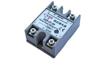
Solid State Relay, SSR
A solid state relay is an electronic switch that switches on or off according to an external signal - it is like an electronic form of electromechanical relay.
Home » Electronic components » this page
Relay Technology Includes:
Relay basics
Reed relay
Reed relay specs
Relay circuits
Solid state relay
Solid state relays can be likened to electronic versions of electromechanical relays. The solid state switch has an output that turns on or off according to the signal applied to the input.
Another attribute of solid state relays is that they provide electrical isolation between the input and output circuits as do the more traditional electromechanical relays.
Solid state relays have a number of advantages over relays, providing faster switching, greater reliability and longer life, etc. but they also have som drawbacks when compared to the more traditional electronic components.
In view of their advantages, solid state relays are being used increasingly as they provide a far more cost effective solution for many electronic circuit designs, especially when the service of the equipment is considered.
Solid state relay basics
Solid state relays can have a variety of different devices at the core of their electronic circuits: thyristors of SCRs, triacs, bipolar junction transistors, BJTs, and MOSFETs provide ideal electronic switches within the solid state relay.
To provide the switching signal between the input and the switching element, an optical link is normally used. This gives virtually complete electrical isolation between the input and output circuits.
Often the switching device; thryristor, triac, bipolar junction transistor or MOSFET is an optical version of the device that turns on in the presence of light.
Essentially the solid state relay is a switch where the input or control voltage lights up a light emitting diode. This acts as the transmitter of an optocoupler which then controls a switching device: thyristor, triac, bipolar transistor of MOSFET.

The solid state relay comprises a transmitter, Tx, and receiver, Rx. These are physically positioned within the solid state relay. The incoming control signal energises the LED within the optocoupler and this illuminates the output switching device which is photosensitive and this causes it be switch over from its normally non-energise state. Typically it switches the output device on, allowing current to pass through the SSR output.
The transmitter and receiver are typically located within the same electronic component, simplifying the construction of the solid state relays.
It can be seen from the diagram that there is no electrical connection between the input and output electronic circuits. This separation, often called galvanic separation is key to keeping the input and output circuits isolated from one another. The galvanic isolation between the LED and photo-device is typically in the range of several thousand volts due to the separation between the optical transmitter and receiver or detector device separation, and an optically transparent insulating barrier which is placed between them.
When looking at the SSR specifications, it is worth noting that isolation is specified in terms of the voltage breakdown, i.e. the voltage that causes breakdown between the input and output. It is not the same as input to output resistance. Dependent upon the device this can be anywhere between 1000 to 1 million MΩ - as it is so high it is often considered to be an “infinite” resistance.
Although the basic concept diagram of the solid state relay only shows an LED that illuminates an light sensitive semiconductor switch like a thyristor or SCR, a triac, transistor or MOSFET, there are also other components that are required within the SSR.
There are two main areas of the solid state relay:
- SSR input: There are a number of aspects of the input circuit to consider as the input LED needs to operate under the required input conditions:
- Input drive level: The input circuit needs to ensure that the optical transmitter, i.e. LED is able to operate wit the specified drive level. This normally requires the inclusion of a current limiting resistor and any other electronic components to ensure the LED lights sufficiently with the incoming signal. Solid state relays are available that operate with input voltages of anywhere from a few volts upwards.
- DC or AC input: If the SSR is intended for operation with a DC input then it can operate with a minimum of additional electronic components - possibly just a current limiting resistor. If AC operation is intended, then a rectifier and normally a bridge rectifier is used to rectify the input signal so that the LED is only driven with a signal of the correct polarity. The LED light will pulse with the alternating waveform - twice the frequency if a bridge rectifier is used. This bridge rectifier can be incorporated as part of the solid state relay, or possibly added externally.
- SSR output: The output side of the solid state relay also requires understanding as there can be a number of additional electronic components beyond the basic photo-sensitive switching device.
A variety of different devices can be used for the output of solid state relays: transistors, thyristors / SCRs, MOSFETs and triacs. The device type determines many of the characteristics of the SSR.
If the output is a single transistor, FET or thyristor / SCR then this means that this SSR can only conduct in one direction and can only be used for controlling DC loads. A triac or two thyristors / SCRs in the output are generally required for AC operation - paired MOSFETs are also sometimes used.
The specified maximum output ranges for solid state relays can range from a few volts up to hundreds of volts AC or DC and the current levels that can be carried can be up to tens or even hundreds of amps according tot he specification of the particular device.
Synchronous & random switching solid state relays
When switching high currents and using semiconductor devices that can turn from off to on very quickly gives rise to sharp edges on waveforms. In turn this can lead to high levels of electromagnetic interference, EMI. As all devices these days must be designed to minimise this interference, it is necessary to utilise ways that minimise the generation of this EMI, so that the electromagnetic compatibility, EMC performance of the device falls within the required limits.
One method that can be used with AC and resistive loads, is known as synchronous or zero crossing switching. As the name indicates the solid state relay only turns on or off at the zero crossing point of the AC waveform irrespective of the input control signal timing.
Whilst zero crossing SSRs are ideal for resistive loads, they do not work properly with inductive loads because the current and voltage are out of phase. Often they do not turn off properly.
For inductive loads, like transformers and motors, it is normal to use random switching solid state relays. These devices turn on or off at the instant required by the input control signal and they do not take account of the position on the waveform.
Advantages & disadvantages of solid state relays
As with any technology, there are advantages and disadvantages to their use. This is true for solid state relays - whilst they offer many advantages over other alternatives like electromechanical relays, they do have some drawbacks. The actual choice of technology must be considered looking at all the options so that the right choice is made.
Advantages of solid state relays
- Provides physical isolation between circuits.
- Faster switching than electromechanical relays. Switching time is typically around 1 ms
- Higher life expectancy than for electromechanical relays
- They do not suffer from the contact bounce experienced when using electromechanical relays.
Disadvantages of solid state relays
- Resistance in the output circuit is normally higher than that of an electromechanical relay
- Not as resilient to transient spikes and other overload conditions as a mechanical relay - unless protected, a transient above the limits of the output device could destroy the solid state relay.
Comparison of solid state relays with electromechanical relays
In many electronic circuit designs there is a choice between the more traditional electromechanical relays and solid state relays. In many ways the two technologies are very different, but in a large number of circuit designs there is the possibility of using one or the other.
To make the best choice for any given electronic circuit design, it is best to look at both options, comparing the advantages and disaadvantages of both option.
| Parameter | Electromagnetic relay | Solid State Relay |
|---|---|---|
| Sensitivity to misuse | Good | Poor |
| Sensitivity to corrosion, oxidation, etc | Poor | Good |
| Sensitivity to shock & vibration | Poor | Good |
| Cost per pole | Better | Not so good |
| Compatibility with logic / digital circuitry | Poor (requires interface) | Good (can be built in) |
| Operate & release times | 5 - 20ms | 0.25 - 10ms |
| Ease of fault finding | Good | Poor |
| Input to output isolation | Often up to 5kV | <5kV |
| Normal failure mode | Open circuit (& large contact wear / high resistance) | Short circuit |
How to select a solid state relay
When selecting which solid state relay to use it is first necessary to define what it needs to be able to switch and how this needs to be achieved. There are a few useful steps to take and questions to ask:
AC or DC: There are different types of solid state relay used for switching AC or DC. Determining whether AC or DC power is to be switched is one of the most fundamental selections. As AC solid state switches typically use triacs and thyristors they do not work on DC and would not turn the load off, unless the DC falls to zero for some other reason. DC solid state switches typically use MOSFETs as they have a very low ON resistance.
Also remember that the input and output may be different - an SSR may be designed to control an AC output, but require a DC control voltage input, etc. In some instances a bridge rectifier, and possibly other electronic components may be required on the input to create the required control signal if they are not contained within the SSR package - check the specification to find out what may be needed.
Voltage range: It is necessary to determine the required voltage for the SSR. If DC is to be switched then select a solid state relay with at least 25% greater voltage rating than the maximum voltage anticipated. Ideally a greater margin would improve the reliability.
For AC SSRs, the AC voltage required for the application should be checked - again add a margin. Even though transients are present on many AC lines, AC solid state relays should be able to accommodate these as they are likely to have inbuilt protection (see below), but it is always best to check the specification.
- Load current: Apart from the voltage, it is also necessary to know the current that will pass through the device. If too much current flows through the device then it will overheat and could be destroyed.
One point of which to be aware is the inrush current that many circuits exhibit. When first turned on, some items can draw levels of current that far exceed the average current drawn. It is therefore necessary to allow for this when selecting the solid state relay. Typically a multiplier is applied to the average current dependent upon the load which is being switched.
Load to be switched Multiplier Fluorescent lights (AC) 10 Incandescent light bulbs 6 Motors 6 Resistive heaters 1 Transformers 20 The average current to be consumed should be multiplied by the multiplier and the solid state relay chosen with this value for the current.
- Dimming: If dimming is required, then some forms of solid state relay are able to provide a dimming function where the output is controlled by the level of the input.
Load type (AC): For AC loads it is necessary to know whether the load is inductive or resistive. For resistive loads, zero crossing switches can be used. As the name indicates, zero crossing switches switch at the point where the waveform passes through the zero voltage point. This produces a much better switching action and reduces the levels of interference, EMI, generated as well as the level of back emf generated.
If the load is inductive, as in the case of transformers, motors and fluorescent lights, a form of switch called a Random Turn On solid state relay is needed. This turns on at any point in the waveform, as the voltage and current have a phase difference and this causes zero crossing switches to malfunction.
Zero crossing solid state relays can be used with resistive loads like heaters, incandescent bulbs, etc - even though these will have a small inductive element, they are still fine for zero crossing switches. Zero crossing turn off can be inherently provided by triacs or thyristors as they stop conducting at the end of the cycle and need to be retriggered to turn on.
- Surge protection: If the solid state switch is to be used with AC, check that it has surge protection built in - although most of the electronic components intended for use where surges may be present have it built in, it is always best to check the specification sheet. Surge or transient protection is normally provided using metal oxide varistors, MOVs. These metal oxide varistors absorb the transients and prevent them from damaging the SSR.
These points provide most of the major points to be considered when selecting a solid state relay. It is always good to read the whole of the SSR specification to ensure that there are no points that might adversely affect the operation of the overall circuit when in operation.
Solid state relays are ideal devices for many switching applications - they are faster and generally more reliable than electromechanical relays, although they are less resilient to transient spikes and other overload conditions.
In view of their superior operation in many scenarios, solid state relays are used in many circuits, with current and voltage ratings being available for many switching applications.
 Written by Ian Poole .
Experienced electronics engineer and author.
More Electronic Components:
Batteries
Capacitors
Connectors
ADC
DAC
Diodes
FET
Inductors
Memory types
Phototransistor
Quartz crystals
Relays
Resistors
RF connectors
Switches
Surface mount technology
Thyristor
Transformers
Transistor
Unijunction
Valves / Tubes
Return to Components menu . . .


