
Reed Relay & Reed Switch
A reed relay is a type of relay that uses an electromagnet to act directly on reed-like contact of a reed switch contained within a glass envelope, typically bringing the reeds together to make contact when the electromagnet is energised.
Home » Electronic components » this page
Relay Technology Includes:
Relay basics
Reed relay
Reed relay specs
Relay circuits
Solid state relay
Reed relays and reed switches are used in many areas where smaller, faster acting relays are needed in an electronic or electrical circuit.
Reed relays are small and fast acting; they require a much lower level of power to actuate them than other traditional types of relay and as a result they find many uses in various forms of electronic circuits.
In addition to this, reed relays or reed switches can be made much smaller than traditional forms of relays, although their current capability is less, but they still provide an attractive proposition in many instances.
A further advantage of reed relays is that they can offer higher levels of reliability than other relays because of their simplicity and few moving parts, but still being mechanical, they are not always as reliable as fully solid state relays and switches.
Development of the reed switch and reed relay
The concept for reed switches was first proposed in 1922 by a professor at the Leningrad Electrotechnical University called V. Kovalenkov. He proposed the idea of what was termed a magnetically controlled contact which switched under the influence of a magnetic field.
The next developments occurred around 1936 when, in the USA, the Bell Telephone Laboratories launched research into reed switches with a view to using them in telephone exchanges, etc.
By 1938 an experimental switch was used to switch the centre conductor in a coaxial cable and two years later in 1940 the first production devices were available.
Further use of these devices started to manifest themselves in the 1950s when reed relays, i.e. reed switches with their associated electromagnetic coils started to be used for automatically operated exchanges. These reed relays provided significantly higher levels of reliability that their electromechanical relay counterparts and they were also faster, smaller and required less current.
In 1963 the Bell Telephone company introduced its first reed relay based exchange and in the following years, the uptake of this technology for telephone exchanges increased.
With the availability of reed switches and reed relays, they started to be used in a variety of other applications. The switches could be used along with small magnets for various position sensing applications, as well as for use in test and measurement matrix switches. In addition to this, reed switches and relays were used in a host of other applications.
Video: Understanding Reed Switches & Reed Relays
What is a reed relay made of
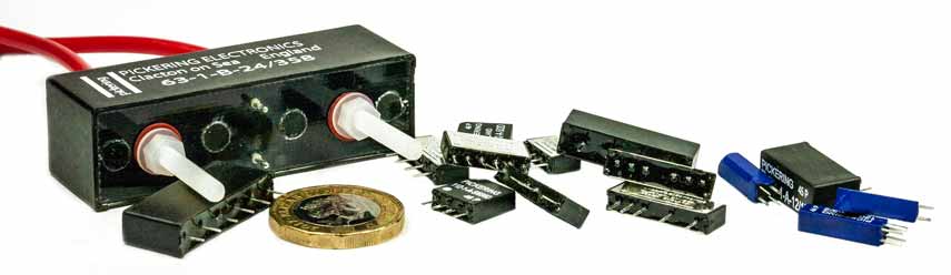
The basis of any reed relay is the reed switch itself - this is the core element of the reed relay. A reed switch consists two reed contacts, typically made from nickel-iron and then plated with materials to ensure the maximum life to the device.
The reed switch contacts overlap so that when they close they make contact with each other. Normally the spacing in the open state is between 0.05 and 1 mm. The greater the spacing, the greater the voltage withstand.
The small gaps between the contacts enable very fast switching speeds, often from around half a millisecond to a few milliseconds dependent upon the actual size, etc of the contacts.
Often the nickel-iron allow is around 52% nickel. The reed contact materials used include ruthenium, rhodium and sometimes iridium or where high voltages are involved it might be tungsten or molybdenum. Often rhodium is usually electroplated onto the reed element, whereas ruthenium is generally sputtered. There were also a very few reed switches that used gold, often for audio - but the low melting point of gold meant they used to stick and they are not seen these days.

The assembly is surrounded by a glass envelope to give a hermetic seal to prevent the ingress of moisture and other contaminants. Most reed relays and reed switches are contained in a glass tube - the individual tubes are cut from a much longer tube. The individual tubes for each reed switch are melted at either end, to provide a hermetic seal.
Typically the glass envelope is filled with an environment to prevent wear, oxidation and better quenching of any sparks.Typically nitrogen is used and this may have a trace of helium. High voltage reeds may use a vacuum.
As the contacts do not slide across each other, there is no form of cleaning, and any pitting tends to progressively build up. To reduce this as much as possible, the cleanliness of the environment within the glass is very important. It is also necessary to maintain the inert gas within the envelope. It is important to ensure that the seal around the glass is maintained, and as a result the areas of the reed contacts that are in contact with the glass are sometimes coated with materials that provide a better seal than the nickel alloy used for the reeds. Another approach is to oxide the reed material int his area.
How does a reed relay work
The operation of the reed relay is quite straightforward. It works by placing a magnetic field close to the reed switch contacts. This causes each of the reeds to become magnetically orientated such that the two ends of the reed attract each other and move together closing the contact.
Under conditions where no magnetic field is applied, the two contacts will not be magnetically orientated and the spring loading in the contacts will keep them apart.
As a magnetic field, for this explanation a bar magnet is shown and although this is not normally used it will work well.
As the magnets is brought closer to the reed contacts which are made of a magnetic material, typically nickel iron, this starts magnetically orientated the two reed relay contacts. A north pole will appear in one contact and a south in the other.

As the magnetic field close to the contacts increases, so too does the strength of the magnetisation of the contacts. Ultimately a point is reached where the magnetic attraction starts to overcome the spring in the contacts. As the contacts move nearer, so the strength of the attraction increases progressively increases, and so a firm contact is ultimately made.
However the speed with which the reed switch contact approach one another does mean that contact-points collide with considerable energy so that they rebound, collide again etc for a while causing a phenomenon called contact bounce.
The way in which the contacts bounce depends largely upon the size of the reed switch, the weight of the contact-elements, their elasticity, etc. Obviously the bounce period significantly increases the wear of contact-elements. The contact bounce can give rise to arcing if current is being carried, especially if there is a capacitive or inductive element to the circuit being switched. Even when switching small currents for items like CMOS or other circuits, the capacitive element introduced by decoupling capacitors on the circuit can cause very high transient currents to occur which can significantly reduce the contact life.

When the external magnetic field is removed, the magnetisation of the nickel iron will also be removed. This will result in the magnetic attraction between the two contacts disappearing, and the spring in the contacts will force the contact apart.
Rather than using a bar magnet as shown for the purposes of the explanation, a coil is normally used - this assembly then becomes the whole reed relay, i.e. a reed relay is the reed switch with the actuating coil. The whole assembly is the reed relay.
As current is passed through the coil, so this creates a magnetic field and the contacts become magnetised, and are attracted to each other. As the field is increased, a point is reached where the contacts close. Removing the current removes the field and the contacts then spring apart.

Using a coil has the advantage that this can be driven by electronic circuitry to enable the reed relay contacts to be controlled or switched by an external electronic stimulus. In this way a small current can control a much larger current passing in the reed contacts.
Reed relay screening
One of the issues that can occur with reed relays is that there is magnetic coupling from the coil. Each reed relay assembly will have an associated magnetic field that extends beyond the mechanical confines of the relay itself.

If the magnetic field is not contained, then the field from an adjacent relay or relays can oppose the field within the relay in question. The arrows on the field that pass through the centre of the coil are in the different direction to the external ones. As the internal field from the coil will be affected by the external field from an adjacent relay, these can be understood to oppose one another.
The field cancellation effect reduces the sensitivity, requiring a higher voltage to ensure reliable switching. With close packed relays, an increase of 30 to 40% of the coil voltage would not be an unreasonable figure, and this may exceed the ratings for the relay and also result in excessive heat dissipation.
Poor screening can also give rise to excessive pickup in other circuits and this may impact the EMC performance.
To overcome this issue, reed relays normally have a ferrous metal screen placed around them. The ideal properties for the shield are for it to have a high permeability and very low magnetic remnance. The screen concentrates the magnetic field and this improves the efficiency of the relay and allows the devices to be closely stacked.

Advantages and disadvantages of reed relays
Reed relays offer many advantages and can be used to good effect in a number of situations. Like many technologies there is a balance to be made between the advantages and disadvantages to determine the applicability for any given situation.
Reed relay advantages
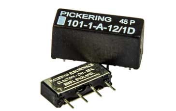
- Small size some are fitted into SIL, DIL packages etc or even smaller
- Fast switching speeds
- Provide complete isolation between the switching current and the switched circuit
Reed relay disadvantages
- Generally a low current capability, i.e. not suitable for very high currents
- Not as fast as some solid state switches, although many solid state switches use opto-isolators which are slow
- As electromechanical devices, they wear with use, especially the contacts
Reed relays are a very reliable form of relay that can be used in a variety of areas. Often they are used in switching matrices were complete isolation and low contact resistance are required.
Their comparative small size and the fact that these relays are often contained within small packages, some the size of a IC dual in line packages or even smaller, means that they are easy to use, convenient, and small enough to be used in virtually any electronic circuit.
 Written by Ian Poole .
Experienced electronics engineer and author.
More Electronic Components:
Batteries
Capacitors
Connectors
ADC
DAC
Diodes
FET
Inductors
Memory types
Phototransistor
Quartz crystals
Relays
Resistors
RF connectors
Switches
Surface mount technology
Thyristor
Transformers
Transistor
Unijunction
Valves / Tubes
Return to Components menu . . .


