
Understanding Reed Relay Specifications & Parameters
Reed relays have a number of specifications and parameters that t is important to understand when selecting a component for a given circuit or application.
Home » Electronic components » this page
Relay Technology Includes:
Relay basics
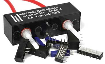
Reed relay
Reed relay specs
Relay circuits
Solid state relay
Reed relay specifications are different to those of other components normally found in electronic circuits. They have some parameters that can affect the operation of the circuit, and if the right reed relay is to be chosen, its specification needs to be understood.
Reed relays obviously have many similarities to the more standard forms of relay, but their size and the applications for which they are used, often means different parameters may be seen in their data sheets.
Reed relay specifications and parameters
Some of the main specifications and parameters for reed relays are given below:
- Coil resistance: The coil resistance is a key parameter for any reed relay. The resistance governs the current that will flow through it when the relay is active or on. As the resistance of the coil will vary somewhat with temperature, the resistance is normally quoted for a temperature of 25°C. The variation of coil resistance may be quoted in the datasheet.
- Coil voltage: This specification details the voltage that needs to be applied across the coil for the reed relay to switch correctly. A temperature is normally specified as the resistance will increase slightly with temperature and this will reduce the current and hence the induced magnetic field. As a result at higher temperatures, the applied voltage may need to be a little higher.
Reed relays are normally available for standard voltages: 3, 5, 12, and 24V are popular voltages and are standard across many ranges. - Maximum carry current: This specification relates to the maximum current that the reed contacts can take when they have switched. As the contacts are of finite size and also they do not make as good contact as a continuous wire, care must be taken not to over stress the contacts. The maximum carry current specification should not be exceeded otherwise pitting and damage will occur to the contacts, reducing the life expectancy.
- Max switch current: Switching a current whilst it is ready to flow or flowing causes more stress both e contacts. As a result the switching current is always less than the carry current. Typically the switching current will be less than half the carry current.
- Maximum switch voltage: This specification details the maximum voltage that the reed relay is capable of switching. Conditions for this specification should be included in the datasheet.
- Operate time: The reed relay operate time specification defines the time taken from the application of the voltage to the coil to state when the relay contacts have settled. The operate time specification is determined by the rate of rise of the magnetic field which determined by the coil inductance and then the inertia of the reed switch blades due to their mass and compliance. After this there is a settling time for the reed blades as they will bounce a few times before settling. The bounce time for small reed repays is often within the region 10 to 50 µs Overall figures of operate time can be as low as 100µs although it is more often around a few milliseconds dependent upon the actual reed relay. The operate time normally includes both the time to initial contact and also the bounce time, but refer to the actual data sheet for clarification of a given reed relay. At high temperatures, the operate time will increase a little due to the increase in coil resistance.
- Release time: The release time specification for the reed relay is the time taken for a relay contact to open after the operating coil has been de-energised. This time is affected by the presence of a protection diode used across the coil. If no diode is present, the release time is improved, but if a diode is used, ten the release time will be around half of the operate time. Check the data sheet for the actual times and the conditions under which the measurements were made.
- With or without diode: A diode is often needed across the coil in the reed relay to suppress the back EMF when he current is removed from the coil. Especially when driven by semiconductor devices, this back EMF can be large enough to destroy any driver transistors. Whilst diodes are often connected externally, they may also be incorporated within the relay itself. Having the diode connected as close as possible to the relay coil improves its performance and also means that one less component is needed on the board. It does make the relay polarised because, if placed incorrectly on the board, the diode will be in forward conduction when the relay is meant to be activated, and hence it will not work.
- Thermal EMF: The thermal EMF of a reed relay or reed switch is the small EMF that appears across the contacts as a result of temperature differences within the switch or relay when the switch is closed. The voltage arises as a result of the Seebeck effect and it occurs.
This means that if one end of the wire is at a different temperature to the other, then there will be a voltage across it, the magnitude of it which is dependent upon the temperature difference and the materials that make up the wire. As reed relays use a number of different details within the reeds, these can have different temperature drops across them and this can result in a voltage appearing at the relay terminals. It should be noted that the thermal EMF voltage is not created at a connection junction, but across the whole of the reed switch. As nickel iron is normally used as the basic material for reed switches and it has a relatively high thermoelectric EMF, this means that designing reed relays with low thermal EMFs is not easy. - Capacitance across open switch: As the reeds in the relay are physical leads, there will be a certain capacitance between the contacts when they are open. This can lead to some signal passing across the open contacts. Values of 0.1pF are often seen. This value is for the basic reed switch without the presence of the coil.
- Capacitance to coil: As the coil is wound around the reed contacts on the exterior of the glass encapsulation, there is a level of capacitance between the reed contacts and the coil. This is typically measured from the closed switch to the coil and may be a low number of picofarads. When a reed relay is used rather than just a reed switch, capacitance path of contact to coil and then coil to there other contact normally dominates over the capacitance across the reed switch contacts on its own.
- Life expectancy: As reed relays are electromechanical devices, they have a life expectancy. This parameter is often detailed in the specifications in the datasheet, and careful note of the conditions for end of life should be taken. Typically the life expectancy is specified in terms of the number of operations, e.g. 108 and the conditions determining end of life detailed, often as a contact resistance, say 1Ω However the life expectancy is very dependent upon the type of load being switched. If there is an inrush current due to capacitance or an indicative load causing arcing, this will significantly reduce the life.
Understanding the specifications and data sheet parameters for reed relays and their constituent reed switches is key to selecting the right component. Being aware of the pitfalls and the specification methods for reed relays can ensure that the best option is chosen.
 Written by Ian Poole .
Experienced electronics engineer and author.
More Electronic Components:
Batteries
Capacitors
Connectors
ADC
DAC
Diodes
FET
Inductors
Memory types
Phototransistor
Quartz crystals
Relays
Resistors
RF connectors
Switches
Surface mount technology
Thyristor
Transformers
Transistor
Unijunction
Valves / Tubes
Return to Components menu . . .


