Home » Component data » Diode (Schottky) data » this page
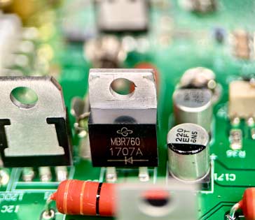
MBR760 Schottky Diode Data
Key data for the MBR760 Schottky diode including key electrical parameters, performance, features, outline, package type and many other key datasheet details.
The MBR760 is one of a series of Schottky diodes that provides a 60V reverse voltage, 7.5A forward current and a 0.75V forward voltage at its rated current of 7.5A.
Key details and datasheet performance parameters for the MBR760 diode.
| MBR760 diode datasheet parameters & data |
|
|---|---|
| Parameters | Details |
| Diode type | 60V 7.5A Schottky diode in TO220 package |
| Package type | TO220-2 |
| Repetitive peak reverse voltage, VRRM | 60V |
| Working peak reverse voltage, VRWM | 60V |
| DC blocking voltage, VR | 60V |
| Forward continuous current, IF | 7.5A |
| Non-repetitive forward surge current, IFSM | 150A |
| Junction temperature (°C) | -65 - 150°C |
| Forward voltage VF | 0.75V at 7.5A @25°C, 0.65V at 7.5A @125°C |
| Reverse leakage IR | 0.5mA at 25°C at VR 60V & 50mA at 125°C at VR 60V |
Outline & pinout:

Explanation of major diode parameters
| Parameter | Explanation |
|---|---|
| Repetitive peak reverse voltage, VRRM | This is the maximum value of the short period peak reverse voltage that can be sustained. |
| Working peak reverse voltage, VRWM | This is the maximum value of the continuous reverse voltage that can be applied to the diode. |
| DC blocking voltage, VR | This is the maximum reverse DC voltage that should be applied across the diode. |
| RMS reverse voltage, VR(RMS) | As many AC waveforms are quoted in RMS, this is the maximum reverse voltage that can be sustained where the voltage is expressed in terms of its RMS value. |
| Forward continuous current, IF | This is the maximum forward current that can be sustained by the diode. |
| Average rectified current, IF | This is the maximum average current value that can be handled by the diode. The parameter often states the load as this will affect the operation of the diode. |
| Non-repetitive forward surge current, IFSM | This is the maximum surge current that can be handled - it should only be present for a short time. |
| Parameter | Explanation |
|---|---|
| Power dissipation, PTOT | The maximum power dissipation that can be sustained within the device. |
| Junction temperature (°C) | This is the maximum temperature of the PN junction that can be sustained. Remember that the junction temperature can be much higher than the ambient temperature of the equipment. |
| Forward voltage VF | This parameter gives the forward voltage drop for a particular current passed through the diode. |
| Breakdown voltage VBR | This is the minimum voltage at which the diode may breakdown. If the current is not limited it will lead to the destruction of the device. |
| Leakage current IR | This is the current that flows under stated conditions when the diode is reverse biassed. |
| Diode capacitance CD | The diode capacitance, CD may also be referred to as the junction capacitance, CJ. All diodes have a certain capacitance across the PN junction. The value will be stated for a given reverse voltage. |
| Reverse recovery time | If a diode is initially driven in forward bias, and the polarity suddenly switches to reverse bias, the diode will still remain conducting for some time. The reverse recovery time is the time required for conduction to settle into the reverse bias state. |
These are the main Schottky diode parameters that have been included in our list. There are others, but these help quantify the main elements of the performance of the diode.
Please note, that the data given is the best estimate we can give within a tabulated summary of this nature. Parameters also vary between manufacturers. Electronics Notes cannot accept any responsibility for errors, inaccuracies, etc, although we do endevaour to ensure the data is as accurate as possible.
Notes and supplementary information
• Availability & sources
The MBR760 is available from a number of stockists and electronic component distributors many of which are given in the table below.
MBR760 Component Distributor, Stock and Pricing
• Notable features
The MBR760 is specifically engineered for high-efficiency power applications, utilising the characteristics of its Schottky barrier construction.
Low Forward Voltage Drop VF : This critical feature, with a maximum of 0.75 V at 7.5A (at 25°C), minimizes power dissipation and heat generation, which significantly improves the overall system efficiency.
High Average Rectified Current (I0) and Repetitive Reverse Voltage (VRRM) : The device is rated for an average rectified current of 7.5A and a peak repetitive reverse voltage of 60V}, making it suitable for medium-power rectification needs.
Low Power Loss and High Efficiency : The fundamental advantage of a Schottky diode is its **metal-silicon junction**, which allows for majority carrier conduction and virtually eliminates the reverse recovery charge, resulting in fast switching with minimal power loss.
High Forward Surge Capability (IFSM) : With a peak non-repetitive surge current of up to 150A (8.3 ms half sine wave), the diode is rugged and can reliably withstand short-duration current transients.
Guard Ring for Over-Voltage Protection (OVP) : An integrated guard ring structure provides enhanced reliability and long-term stability by protecting the diode junction from transient voltage spikes.
High Operating Junction Temperature : The device is capable of operating with a maximum junction temperature TJ of 150°C, allowing for robust performance in demanding thermal environments.
• Typical applications summary
| Application Category | Typical Use Case | Device Feature Utilised |
|---|---|---|
| Switching Mode Power Supplies (SMPS) | Secondary rectification and output stage rectifiers in low voltage, high-frequency converters. | The low forward voltage drop and high-speed switching (due to virtually no reverse recovery time) minimize energy loss during the rectification process. |
| DC/DC Converters | Output rectification and overall use in high-efficiency DC/DC conversion circuits. | The low power loss and high efficiency characteristic are key to achieving high-density power conversion in compact designs. |
| Freewheeling Diode Circuits | Used across inductive loads in motor drives, relays, or high-frequency inverters to protect switching components. | The **high-speed switching** enables quick conduction of flyback energy, and the **low forward voltage drop** minimizes the power dissipated during this phase. |
| Polarity Protection | Preventing damage to sensitive circuitry from accidentally reversed power connections (reverse battery protection). | The low forward voltage drop minimizes voltage loss in the normal, protected path, while the diode's reverse blocking capability provides protection. |
 Written by Ian Poole .
Experienced electronics engineer and author.
Return to Component Data menu . . .