Crystal Radio Circuits: Crystal Set Circuits
A variety of different types of circuit were used for vintage crystal radios of the 1920s and 1930s – many of these can be replicated today.
Crystal Radio Sets History Includes:
Crystal radio sets
Crystal radio circuits
Crystal detector
Crystal radio components
Iconic radio receivers:
Summary of iconic radio receivers
Radio receiver history
Radio history / timeline
There are many different circuits that have been used for vintage crystal radio receivers or crystal sets over the years.
The main design constraint for crystal radio sets is that they are limited by the level of signal picked up by the antenna.
As crystal radio sets are powered directly by the received signal, they have to make the optimum use of the incoming signal from the antenna. This means that the circuits must operate as effectively as possible, directing as much signal as possible into the headphones / earphones.
This means that the design must be undertaken as carefully as possible, balancing all the constraints to give the best circuit.
There are still some vintage radios available in the collectors markets that are based on the crystal radio principle and their circuits give a fascinating insight into the technology of the day.
Elements of crystal radio set circuits
In order to be able to build a more effective crystal radio set, it is necessary to look at the individual circuit elements fully.
It is taken as a given that a crystal set will be using an external end fed wire antenna as this is the most widely used for of antenna for them. Also a good ground syste is also needed to ensure that the antenna operates efficiently. Investment in a good antenna will ensure the crystal radio circuit operates to its best.
Antenna coupling
There are many different ways of coupling the antenna into the crystal radio set. Some circuits just connect the antenna directly to the main tuning, whereas others employ methods to try to obtain the optimum performance from the antenna.
Some circuits use some form of impedance matching either by using an additional winding on the main tuning inductor, or a tap in the inductor. Others use a fully resonant circuit to bring the antenna itself to resonance.
Normally end fed wires were used and for resonance, the antenna should be a quarter wavelength long. For a signal operating at the high frequency end of the medium wave band, a length of around 150 feet is needed for resonance, and this was often too long for many domestic situations. Also the length would need to be altered as the crystal set was tuned to different frequencies. This was clearly not a viable solution.
The solution was to use an antenna tuning circuit in the crystal set. Its purpose was to ensure that the antenna was brought to resonance and its impedance was matched to the remaining circuits in the radio.
Often a simple series tuned circuit is used. A variable capacitor with a maximum capacitance of around 500pF combined with an inductance of around 250µH will enable the medium wave band to be covered very well.
Main tuning and detector coupling:
The main tuning and coupling to the detector are an important element of the crystal radio circuit.
The main tuning is used to peak the signal and reject others that are not wanted. Sometimes capacitors for both the "main" tuning and antenna matching may be used. There can sometimes be an advantage to this, but the two capacitors interact with each other and tuning can be more difficult.
When designing a tuning circuit, the values should be chosen to resonate over the frequency range required. It is worth remembering the standard formula for the resonance of a coil and capacitor:
Using the formula select the inductor value to give the chosen frequency range with the value range for the variable capacitor.
Signal detector:
A variety of different signal detectors were used. One of the main requirements was that they were able to detect signals that were as small as possible.
In the early days of crystal sets, a Cat's whisker would have been used. This used a small wire to create a point contact onto a semiconductor material. This gave what we now know to be a form of Schottky diode which had a low turn on voltage. Today, small signal diodes like Schottky diodes or germanium diodes can be used as these have a turn on voltage around 0.2 to 0.3 volts.
In fact these devices could conduct to a limited extent even at voltages lower than the 0.2 to 0.3 volts, whilst still preventing conduction in the reverse direction. Although they did not operate at their maximum effectiveness for very low voltages, some rectification and hence detection of the signal took place.
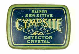
In the halcyon days of crystal radio sets, their circuits could use a variety of different crystals. These different crystals had marginally different properties, but enabled companies to sell a whole variety of different crystals and exploit the possible advantages of each!.
Earphones:
The earphones of headphones used were high impedance ones. Low impedance ones could not be driven by the crystal set circuits as they were unable to source sufficient current.
The headphones that were used with vintage radio crystal sets would have had an electromagnet with a flat steel diaphragm placed just above the magnet sot hat the undulations in current would cause the magnetic field strength to vary and hence this would result in vibrations in the vibrations on the diaphragm.
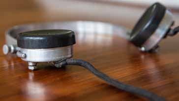
The headphones needed to be high impedance, and often the ones used with vintage radios would be around 2kΩ. However today crystal earphones that use a piezo electronic crystal may be employed. In this way the circuit is voltage driven and does not require much current to be sourced.
The different elements of the crystal radio receiver circuit used a variety of different components. In the early days of radio, these were likely to have been made by the amateur experimenters, although later on, the components became available from radio component stockists who soon started to appear once the demand for radios was established.
Basic crystal radio circuit
The circuits for crystal sets could be very simple. Some simply employed a tuned circuit, a crystal detector and a pair of headphones.
The circuit shown below shows the most basic form of crystal radio circuit. It consists of just four components: inductor and variable capacitor (to form the tuned circuit); diode (to act as the envelope detector); and headphones.
This circuit, whilst easy to make and having very few components, does not provide any matching / tuning for the antenna. It also has the detector and headphones placed directly across the tuned circuit and this will add loading to it, reducing the Q which will reduce selectivity and received signal strength. This type of circuit will only operate with a good antenna and in areas where strong signals are present.

In this circuit the combination L1 with the range of VC1 would have been chosen to cover the required frequency range, typically the medium wave band.
Sometimes a second variable capacitor may be placed between the "ground line" of the crystal set circuit and the real ground. This effectively acts as the antenna tuning, but it is found that the two capacitors interact with one another and tuning can be quite difficult.
Crystal radio circuit employing input transformer
In order to ensure a better signal transfer from one circuit to another it is necessary to match the impedance. In some crystal receiver circuits this was achieved simply by having an additional coil on the same former so that the often lower impedance of the antenna could be matched to the higher impedance of the crystal radio receiver itself.

This arrangement is not perfect because it does not tune the antenna to operate on the required frequency. Nor does it allow for match for the given antenna at the particular frequency of operation. The antenna impedance will vary according to a variety of factors so the match cannot be optimised using this circuit.
Carborundum crystal radio circuit
Carborundum detectors were more reliable than the ordinary galena or other types available. The cat's whisker wire was generally of steel to allow more force to be applied to the carborundum. This made the junction less prone to vibration and also some impurities. This often required a different holder to that used for the other types of crystal.
However the junction did need some forward bias to enable it to operate to its best. This was applied by a batteries and the voltage level needed to be adjustable to ensure the best performance.

The use of carborundum in crystal radios tended to be reserved for the more advanced or specialist radios. As they needed batteries to bias the crystal into its operating region, it added additional cost because batteries were not cheap in the early 1920s and 1930s.
Using tapped coils
One way of reducing the loading of the tuning coil by the detector / headphone combination is to use a tap int he coil and only use part of the coil for the detector. This has the advantage of increasing the Q of the coil and giving a better impedance match to the detector circuit.

Although there is a reduction in loading on the coil, as only a proportion of the voltage that is developed across the coil is available for the detector and headphones the volume can be reduced. It can be a trade-off between volume and loading on the coil.
Many radios would have a switch for the tap on the coil, enabling the user to experiment and obtain the best performance for their particular situation.
Crystal radio circuit using variable coupling
Another approach to improving the performance of the crystal radio circuit is to use a variable coupling between the antenna circuit and the detector tuning.
this offers the possibility of tuning the antenna for best operation, tuning the detector for the required frequency and adjusting the coupling between the two coils to obtain the required Q.
Reducing the coupling between the two circuits will increase the Q of the tuning, and hence the selectivity, but reducing the coupling between these circuits will reduce the sensitivity.

This is a very elegant method for adjusting the sensitivity and selectivity to obtain the required performance.
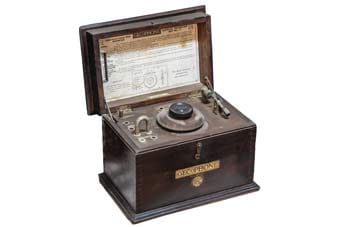
GECoPHONE No 1 circuit
It is also worth taking a look at some of the circuits used by the original broadcast radio receiver crystal sets as these give an insight into the way the technology was at the time. The GECoPHONE crystal set No 1 was launched in 1923, so the circuit is that of a real vintage radio - even an antique radio.
The circuit for the GECoPHONE No 1 crystal set is quite straightforward. The circuit can be seen in the diagram below.
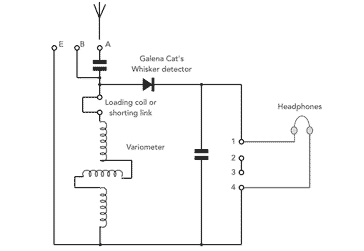
Tuning was performed by rotating a variometer that formed the centre section of the inductor. This varied the inductance of the overall inductor and hence it altered the resonant frequency of the input circuit. The inductor resonated with its self capacitance and that of the antenna.
For long antennas of more than 60 feet, the connection was via a capacitor, bt for shorter ones it was direct. The capacitance tended to counteract the inductance of the antenna.
The detector was a standard form of cat's whisker diode using a wire giving a point contact onto the semiconductor material
During the days when crystal radios or crystal sets were the radio of choice for cost reasons as well as the availability of components, etc, a vast number of circuits came about. They offered the promise of better performance and superior sensitivity and selectivity. However it often boiled down to a compromise between sensitivity and selectivity.
When looking at vintage radios in collections and museums, the variety of ingenious ways of obtaining the best performance provide an insight into the technology that people were using.
 Written by Ian Poole .
Experienced electronics engineer and author.
More History:
Radio history timeline
History of the radio
Ham radio history
Coherer
Crystal radio
Magnetic detector
Spark transmitter
Morse telegraph
Valve / tube history
PN junction diode invention
Transistor
Integrated circuit
Quartz crystals
Classic radios
Mobile telecoms history
Vintage mobile phones
Return to History menu . . .